• WANTED: Happy members who like to discuss audio and other topics related to our interest. Desire to learn and share knowledge of science required. There are many reviews of audio hardware and expert members to help answer your questions. Click here to have your audio equipment measured for free!

Hypex NCx500 Class D Amplifier Review

Rate this amplifier:

  • 1. Poor (headless panther)

    Votes: 3 0.7%
  • 2. Not terrible (postman panther)

    Votes: 6 1.3%
  • 3. Fine (happy panther)

    Votes: 55 11.9%
  • 4. Great (golfing panther)

    Votes: 397 86.1%

  • Total voters
    461

GXAlan

Major Contributor
Forum Donor
Joined
Jan 15, 2020
Messages
3,925
Likes
6,066
Marantz PM-10 Comparison
(bridged NC500OEM with Marantz buffer+preamp)

Source = -111 dB SINAD Panasonic UB9000
Instrument = E1DA Cosmos ADC; Grade A

Edit: I just left this in the 43V input mode. If I matched the input sensitivity of the E1DA to the actual output, you get higher SINAD numbers. I ran the bandwidth from 20 to 22050 Hz instead of 20 to 20000.

My tests are noisier and more distorted that @amirm 's. This UB9000 source / E1DA gives me a Marantz PM-90 measures -79 dB on my system, but Amir testing the identical physical unit (actual unit) got to -87 to -88 dB.

PM90-reference.png


The inflection point for the bridged PM-10 is around 25W.

I wasn't able to get the setup below -102.4 dB SINAD (0.000759%) which is due to my test gear. It's possible that it also has the 5 or 10W inflection point and I just cannot get the nadir as low. The 20 mW and 300W are equal on the NCx500 and the PM-10,

1673923660771.png


I don't see a big difference between ~5W vs ~50W
1673923757997.png


1673923778268.png


But as you go higher, you do see the noise well above 100 kHz
200W and 360W
1673923802498.png

1673923812981.png


For the 19/20kHz IMD, the spikes around the audible range are LOWER than the AHB2 but you have higher spikes above 30 kHz
1673923914405.png


1673923956485.png
 
Last edited:

GXAlan

Major Contributor
Forum Donor
Joined
Jan 15, 2020
Messages
3,925
Likes
6,066
@restorer-john @pma
Are you comfortable with those ultrasonics? Is it far enough for you to avoid the IMD effects? Marantz did spend a lot of time on the PM-10 design. They did go bridge NC500’s even though the SMPS is just the 600. It also has HDAM’s all around.

It seems like the 19/20 kHz IMD in the audible range is impressive, right?

Biggest weakness is my tone generator. 120 Hz spike in the multitone actually comes from the source.
1673929573310.png
 

pma

Major Contributor
Joined
Feb 23, 2019
Messages
4,614
Likes
10,790
Location
Prague
Marantz did spend a lot of time on the PM-10 design. They did go bridge NC500’s even though the SMPS is just the 600. It also has HDAM’s all around.
This (bridged design) is what made the difference and better suppression of noise floor modulation at higher power. Thanks for your effort.

The last question - what kind of LPF filter do you use to cut ultrasonics for your measurements?
 
Last edited:

pma

Major Contributor
Joined
Feb 23, 2019
Messages
4,614
Likes
10,790
Location
Prague
@restorer-john @pma
Are you comfortable with those ultrasonics? Is it far enough for you to avoid the IMD effects? Marantz did spend a lot of time on the PM-10 design. They did go bridge NC500’s even though the SMPS is just the 600. It also has HDAM’s all around.
Once again, my question on LPF filter used for measurements. The speaker does not see any sharp LPF inserted, it sees amplifier output directly. For illustration, I have made a couple of acoustical near field tweeter measurements in my main setup.


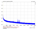
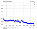
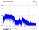
1. NC252MP offNC252MP_off_lin.png 2. NC252MP on NC252MP_on_lin2.png 3. NC252MP playing analog FM radio analog FM_linscale.png

The plots use linear frequency scale. Please see noise modulation in (2). Please see the 19kHz pilot FM frequency in (3), which is the highest in the spectrum. Volume set to standard "background music" level. Plot (3) shows the reason why it is important to measure twin-tone IMD and why one of the test frequencies was chosen at 19kHz, long ago.
 

PeteL

Major Contributor
Joined
Jun 1, 2020
Messages
3,303
Likes
3,846
:confused: /\ the obvious still leaves me \/

without an answer to my question.
"Higher parts reuse = lower costs"? If the majority of use cases would be for a minimum of stereo; then, would the re-use of the same smps for both channels be more relevant and lower costs? Less parts usage also includes the enclosure, and other common piece parts to be shared between L/R.
My guess, is that the original goal was to eliminate as many variable as possible to assess the performance of the module itself (an in effect give it the best chance to shine). Sharing a Power supply with 2 channels is one bit of extra variable. But in the end this can come back to bite, with some justified critics when you see that the addition of a buffer, to make it an actual real useful amplifier, actually gives better distortion metrics, a real line in impedance and enough gain for typical hifi use.

After saying that tough. My main amps are 2 NC500 monoblocs (the original, not the X), that looks just like this thing (ok with a nicer case and a pretty illuminated power button on the front panel), in the end for the same reason, the assurance that I was getting the absolute best performance, the simplest configuration.
 
Last edited:

pma

Major Contributor
Joined
Feb 23, 2019
Messages
4,614
Likes
10,790
Location
Prague
But in the end this can come back to bite, with some justified critics when you see that the addition of a buffer, to make it an actual real useful amplifier, actually gives better distortion metrics, a real line in impedance and enough gain for typical hifi use.
Buffer drives the following circuitry from very low output impedance. This is definitely a big real-world advantage. Who is aware of this fact and who cares?
 

JohnnyNG

Active Member
Joined
Dec 24, 2019
Messages
181
Likes
189
On the other hand, I agree that AHB should be better in the CCIF test.
Intermodulations, guys. Intermodulations in tweeters (and in human ear, if the signal gets in).

Interesting. Since it's been around a while, what might be the reported audible consequences of this regarding the AHB2?
 

PeteL

Major Contributor
Joined
Jun 1, 2020
Messages
3,303
Likes
3,846
Buffer drives the following circuitry from very low output impedance. This is definitely a big real-world advantage. Who is aware of this fact and who cares?
At what impedance the AP analyser drives such circuitry?
 

sarumbear

Master Contributor
Forum Donor
Joined
Aug 15, 2020
Messages
7,604
Likes
7,324
Location
UK
As for only needing 5 watts, why would anyone who only needs 5 watts want a 250w amplifier? The answer seems obvious to me -- they need more than 5 watts.
Especially in classical music dynamic range is in double figures and numbers as high as 38 are measured. That means your 5W average listening requires a 190W amplifier. If you want to listen a bit louder you may need a 400W amplifier to recover the full dynamic range in the recording.

Or look at it this way:

For a speaker with 86dBSPL/2.83V rating you will get around 104dBSPL peaks at a 2m listening position when the 250W amplifier is peaking. Calc. However, your average SPL will be only 84dBSPL at 2m, even using an average crest factor of 10.

High power amplifiers like this one are important to you if you listen to music with high crest factor like orchestral classical music.
 
Last edited:

pma

Major Contributor
Joined
Feb 23, 2019
Messages
4,614
Likes
10,790
Location
Prague
So 40 ohm, my question was the analyser output. I am a bit surprised it would have detrimental effect on driving the module bufferless which is 1.8 kOhms.
You would need to measure output of the AP generator (distortion) when loaded with the DUT nonlinear input impedance. Otherwise it is only guessing. Even 40 ohm output impedance worsens, in some cases, overall distortion, in the real world.
 

BR52

Addicted to Fun and Learning
Joined
Apr 3, 2021
Messages
573
Likes
495
Location
Germany
So 40 ohm, my question was the analyser output. I am a bit surprised it would have detrimental effect on driving the module bufferless which is 1.8 kOhms.
1.8 kOhm 20Hz to 20 kHz ?
40 Ohm 20Hz to 20 kHz ?
 

pma

Major Contributor
Joined
Feb 23, 2019
Messages
4,614
Likes
10,790
Location
Prague
1.8 kOhm 20Hz to 20 kHz ?
How do you know? What do you know about nonlinearity with voltage level? We do not live in the world of simple resistances, guys. And consider we are talking about change like -90, -100 dBr. Change of 1.8 ohm with level is only -60 dBr ….

And now, think about the effect of output impedance of DAC or preamp to such DUT.
 

BR52

Addicted to Fun and Learning
Joined
Apr 3, 2021
Messages
573
Likes
495
Location
Germany
How do you know? What do you know about nonlinearity with voltage level? We do not live in the world of simple resistances, guys. And cosider we are talking about change like -90, -100 dBr. Change of 1.8 ohm with level is only -60 dBr ….
Could you see my question mark?
Edit: in power amps we are taking care of damping factor. Hopefully over the full bandwith
Edit: Pls read my post #73
 
Last edited:

PeteL

Major Contributor
Joined
Jun 1, 2020
Messages
3,303
Likes
3,846
You would need to measure output of the AP generator (distortion) when loaded with the DUT nonlinear input impedance. Otherwise it is only guessing. Even 40 ohm output impedance worsens, in some cases, overall distortion, in the real world.
ok, so just to clarify, I think you have research that a bit more. You are saying that the bufferless added distortion may be caused by an impedance mismatch correct? Even tough the measured frequency response is unaffected returning from the same DUT?

Can you provide just the basic concept or even better, some link for reading material.

Edit: that said I do fully agree that in real world I don't like a Power amp which show input impedance that low. but I am just talking about what was measured here.
 
Last edited:

boXem

Major Contributor
Audio Company
Joined
Jun 19, 2019
Messages
2,020
Likes
4,916
Location
Europe
@amirm has been measuring headphone amps with low input impedance (2k) since a few years now. So we know that the AP has no issue driving 4V RMS into 2k.
10W in 4Ohm is 6.32V RMS. With a gain of 11.5 dB this makes 1.7V RMS at the input. Unless the AP is broken, I do not believe that the problem comes from here.

Do we know how much common mode voltage the AP is outputting?

Edit: I didn't read @pma hypothesis on uneven output impedance. This would create common mode voltage.
 

GXAlan

Major Contributor
Forum Donor
Joined
Jan 15, 2020
Messages
3,925
Likes
6,066
This (bridged design) is what made the difference and better suppression of noise floor modulation at higher power. Thanks for your effort.
Yeah, it’s interesting because the bridged design has an “underpowered” power supply and hifinews said worse 2 ohm and 1 performance compared to the PM-KI Ruby. I really believe they made that decision for better real-world performance.

Marantz marketing: “However, in order to bring out the potential of this excellent power amplifier and realize the sound and quality that Marantz aims for, there are various adjustments to the switching amplifiers - mounting position, accuracy, thermal management, and noise control. So, it took a lot of effort. The PM-10 was completed after a development period of nearly three years, twice as much as usual, but much of that time was spent to bring out the potential of the switching amplifier.

The last question - what kind of LPF filter do you use to cut ultrasonics for your measurements?

No extra LPF filter in the measurements shown. I run the UB9000 into the PM-10 and use the PM-10's volume control to control the wattage into a pair of Vishay Dale 1% non inductive resistors. It's also possible that a HDAM SA3/pre-amp component/or Marantz buffer is doing something too. It was this review that made me realize that the buffer can improve measurements, not just improve gain.

I am not sure anyone else has shipped a bridged HypeX amp. Seems like it would get better measurements and you can sell 2x the amps to a single customer and be an interesting thing for @Rick Sykora to try out? That said, for all we know, maybe the NCx500 does well -- @amirm, can you run one of those 1M bandwidth measurements?

Under the same test setup but at 176 kHz samping for the E1DA, you can see how much worse the PA5 does for ultrasonics (even though it is "great" with the 20-20kHz cutoff). There's clearly a ripple right at the cut off point, which means even going to 22050 would have dropped the computed score).

1673960507731.png
 

BR52

Addicted to Fun and Learning
Joined
Apr 3, 2021
Messages
573
Likes
495
Location
Germany
@amirm has been measuring headphone amps with low input impedance (2k) since a few years now. So we know that the AP has no issue driving 4V RMS into 2k.
10W in 4Ohm is 6.32V RMS. With a gain of 11.5 dB this makes 1.7V RMS at the input. Unless the AP is broken, I do not believe that the problem comes from here.

Do we know how much common mode voltage the AP is outputting?

Edit: I didn't read @pma hypothesis on uneven output impedance. This would create common mode voltage.
Fred, thanks for jumping in.
In the past, with more standardized input impedance, 47k, 22k...., the source was designed to handle it. Now with upcoming low input impedance blocks, the situation starts
to be more complicated as well. Because loads like this will torture the outputs of preamps, DAC's, APxx even more. Maybe causing higher high frequency distortion in the sources as well.
Should we start a new thread, we are coming more off-topic now?
 
Top Bottom