restorer-john
Grand Contributor
What performance Chart? Any measurements?
Follow the link. Click the links. You have a computer, right? It's the left click button on that weird mouse thing...It's not hard...


What performance Chart? Any measurements?
Even if you want to play that way you buy either already soldered PCB's or do it yourself with LJ one's which are mostly actually Yamaha clones and for a fraction of the price.Kit is bit special , the idea is that someone is able to solder it together and roll their own amp for the fun off it.
Industrialized automatic mass production beats artisan work all the time for actual quality for your money.
Maybe someone that knows should open a recommended kits treadit sure must be better ones than this
Check measrements into the shared link by clicking here :What performance Chart? Any measurements?
 www.audiosciencereview.com
Because Randy the Cheapaudioman likes Akitika.so why does it exist? why would someone buy it?
Me thinks the excessive hum is due to the wiring scheme.
The distortion profile is not even that bad. Mostly even order and gradual sloping.
If grounding was done properly it probably would have measured better.
Ground lifter may even make things worse here.
The output cap is also not in the feedback loop, a 100uF polar cap is in the feedback loop.
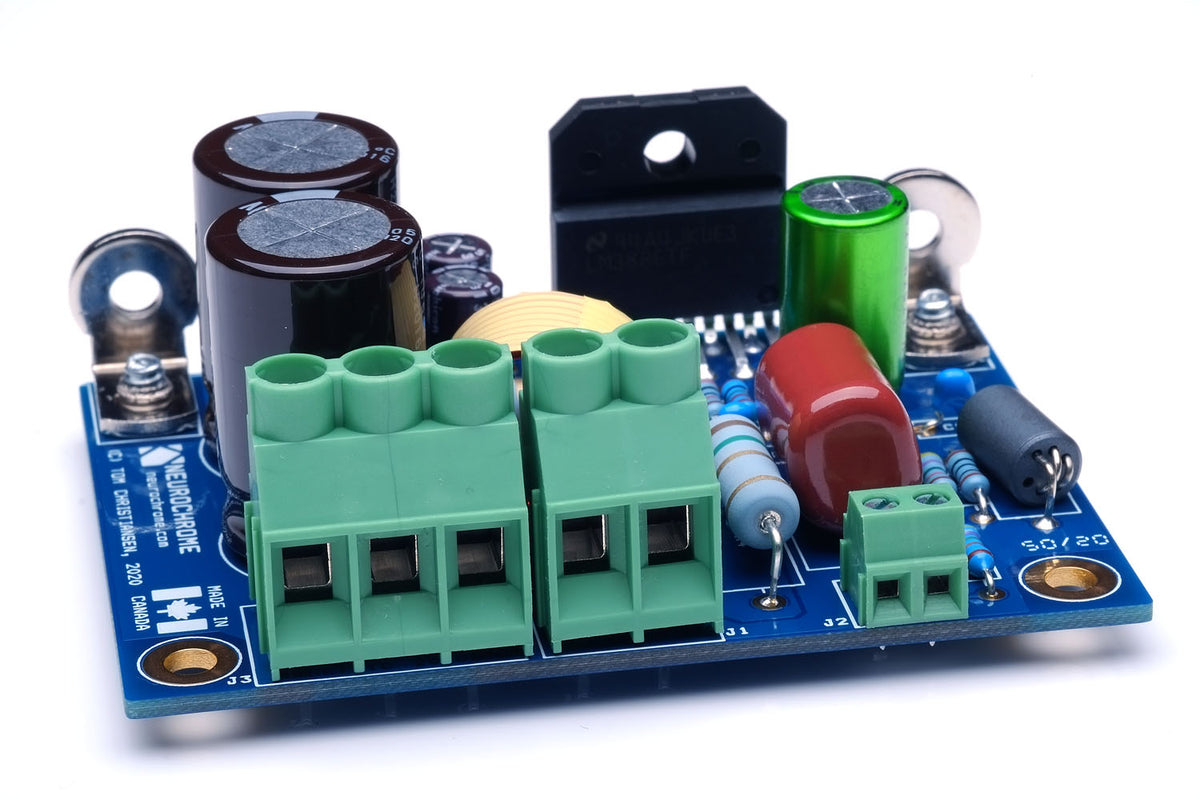
It has 10u AFTER feedback? Why didn't they do a symmetric power supply to avoid that?Here are those big fat 10K micro Farad 63 V capacitors on the amp PCBs.
View attachment 357448
Here are those big fat 10K micro Farad 63 V capacitors on the amp PCBs.
View attachment 357448
Wow, that's expensive.Thanks @amirm
Adding current price:
GT-108 Stereo Power Amplifier Assembled and Tested (GT-108A) - $599 plus $26.00 shipping (48 states)
Overly aggressive current limiting?This is interesting. I suppose the power supply/output impedance(Z) is at fault here. Any thoughts about this anybody.<?>
It's ludicrous compared with a Topping LA90 for the same price.Wow, that's expensive.
I'm not sure. I look at that circuitry and my eyes roll back into my noggin! gg*Overly aggressive current limiting?
I'm leaning to Z and power supply too.It's a regulated supply, single rail amp with capacitor coupled outputs (looks like maybe in the feedback loop) and some clearly quite aggressive current limiting.
This amp appears to have a unipolar PS, hence the need for the large C13 coupling to the speaker to remove the DC offset of about half VCC. To avoid a loud "thump" and speaker overload upon power up, K1 is likely in the O position so that C13 can charge through R35 and R38 to about half VCC. Then K1 is switched to the S position, at which point the internal resistive load (to keep C13 charged) changes to R40. But it seems that the speaker is connected to the OUT terminal, not the L1A point. If so, the 10 Ohm / 1 Watt R35 is kept in series with the speaker, which does not seem a good thing even if negative feedback is connected to L1B. Am I reading the schematic incorrectly?
Is that capacitor inductor for feedback?You missed the inductor (L1) (wound around the cap can) that sits in parallel with the resistor...
