OP
- Thread Starter
- #281
The biggest concern I had once I set up the NFS was the microphone boom as well as the cage. The cage is a safety feature. It isn't intended to be used on the microphone at all times (not my opinion; Christian Bellman verified this when I had as Skype session with him and asked about it specifically a few days ago).
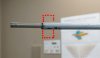
For those who do not know what that is, here are a couple photos of the mic/cage:


This is what the mic looks like without the cage:

The obvious thing was to measure a speaker with and without the mic cage. I used a laser level and calipers to make sure the mic was placed in the same position in both cases.

And here are the results.
Blue = Mic with cage
Red = Mic without cage

As expected, there is a comb filter pattern high in frequency ~6kHz and above. The red response (without cage) is more smooth without large deviations, whereas the blue (mic with cage) shows +2dB variation at about 9kHz as well as other pattern issues.
**************
**************
So, yea, the mic cage creates some combing issues. But, the microphone without the cage isn't without its own issues. The simple fact that the microphone is hanging off a fixture which is attached to the boom creates a path length of about 5 inches from the mic to the mic boom which creates comb filtering as well. Thus, also diminishing the goal of "absolute accuracy". And, even if this weren't an experiment in trying to achieve a high level of accuracy, it's pretty obvious you don't want that reflection path because it would create response error/inaccuracy.
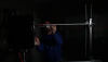
So, the next step was to create a new microphone holder, placing the microphone at the very end of the tube so there was no reflection path between the mic boom/holder and the microphone electet itself as shown below. Now, this isn't the *final* design but it gives you an idea for this discussion.

And here are the results.
Same as above but now with the "mic on new boom" in black.

Notice how much smoother the black line is now, and how it is devoid of any comb filtering? Yep. How much? In this particular case? About ±0.50dB. But this is a single axis measurement and I wouldn't be surprised if the error was higher off axis (especially in the far-field for those who don't use a NFS). Now the real question is: does the tester/engineer care about the deviation from the stock boom with ball joint (or otherwise) vs straight rod or not? Maybe some don't. But I know others do; not just industry but other DIY'rs. And if I am going to go for absolute accuracy, I might as well start with the easiest fix: the boom.
I will clean up the design a bit (as I discuss in the video below) and begin moving on to testing and reviewing speakers.")
For those who do not know what that is, here are a couple photos of the mic/cage:
This is what the mic looks like without the cage:
The obvious thing was to measure a speaker with and without the mic cage. I used a laser level and calipers to make sure the mic was placed in the same position in both cases.
And here are the results.
Blue = Mic with cage
Red = Mic without cage
As expected, there is a comb filter pattern high in frequency ~6kHz and above. The red response (without cage) is more smooth without large deviations, whereas the blue (mic with cage) shows +2dB variation at about 9kHz as well as other pattern issues.
**************
**************
So, yea, the mic cage creates some combing issues. But, the microphone without the cage isn't without its own issues. The simple fact that the microphone is hanging off a fixture which is attached to the boom creates a path length of about 5 inches from the mic to the mic boom which creates comb filtering as well. Thus, also diminishing the goal of "absolute accuracy". And, even if this weren't an experiment in trying to achieve a high level of accuracy, it's pretty obvious you don't want that reflection path because it would create response error/inaccuracy.
So, the next step was to create a new microphone holder, placing the microphone at the very end of the tube so there was no reflection path between the mic boom/holder and the microphone electet itself as shown below. Now, this isn't the *final* design but it gives you an idea for this discussion.
And here are the results.
Same as above but now with the "mic on new boom" in black.
Notice how much smoother the black line is now, and how it is devoid of any comb filtering? Yep. How much? In this particular case? About ±0.50dB. But this is a single axis measurement and I wouldn't be surprised if the error was higher off axis (especially in the far-field for those who don't use a NFS). Now the real question is: does the tester/engineer care about the deviation from the stock boom with ball joint (or otherwise) vs straight rod or not? Maybe some don't. But I know others do; not just industry but other DIY'rs. And if I am going to go for absolute accuracy, I might as well start with the easiest fix: the boom.
I will clean up the design a bit (as I discuss in the video below) and begin moving on to testing and reviewing speakers.
Attachments
Last edited:
 3) bash me up