ctrl
Major Contributor
Open baffle (OB) speakers seem to be becoming more and more popular at the moment. The possible advantages of an OB speaker do not need to be listed here, they can be found on every manufacturer's website or audio forums.
When using or purchasing U-frame or V-frame (and to some degree H-frame) dipole designs, there is a risk that design errors will be made by DIY beginners if the necessary basic knowledge is lacking or speakers are purchased which are faulty designs.
Therefore, simple examples will be used to point this out and help you to avoid these pitfalls.

The examples are based on commercially available speakers. Unfortunate some manufacturers sell faulty designs based on U-frame dipole speakers too.
This is very bitter for the paying customers.
BUT if such a desgin error is made, it does not mean that the entire speaker will sound bad - please keep this in mind for the further sections.
I am not an expert on dipole design of loudspeakers, detailed information on dipole speakers can be found at Siegfried Linkwitz's website.
Before discussing the pitfalls of U/V-Frame (and to some extend H-frame) design, some basic thoughts on OB speaker.
Index
1. classic OB speaker
2. OB speaker - displacement volume is everything
3. Why U- and H-Frame?
4. The U-Frame pitfall
5. H-frame the U-frame killer
6. classic flat OB, U-frame or H-frame Design - OB low bass output?
7. V-frame instead of U-frame - what's the difference?
8. H frame with angled side walls
9. U-frame resonance side effects
1. classic OB speaker
First, let's look at a classic OB design - so we have a reference to compare to. That means a large flat baffle combined with a driver that can move as much air volume as possible.
Example 0
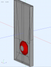
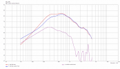
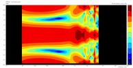
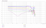
Here the simulation of an OB baffle with height, width, depth of 100cm x 44cm x 7cm (39''x17''x2.8'') with a 10'' woofer - better would be 18'', but for our comparisons this doesn't matter.
The images are,
- Front and back view of the simulated LS with reference axis as blue line,
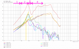
- SPL speaker (red) and woofer front (blue) and back (pink) sound separately in 2m distance,
- Horizontal on-axis normalized sonogram,
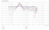
- Horizontal normalized frequency responses 0-90° (10° steps):
The reference example baffle is not ideally flat, but has a very slight U-frame shape to stay as close as possible to real designs (that use this practice to stabilize the baffle).
2. OB speaker - displacement volume is everything
Would like to list it here for the sake of completeness.
If the wavelength is large compared to the baffle, then the frequency response drops by 6dB/oct (compared to a monopole speaker) due to mutual cancellation of front and rear sound.
The consequences have been described by S. Linkwitz:
The larger the baffle, the later this transition occurs.
The sound pressure curve is of course individually different and depends on the baffle and driver size and the TSP values of the driver.
As an example, a simulation of a loudspeaker, with the same baffle and driver, once as an open baffle design and once as a closed box loudspeaker (CB) design.
More details can be found here ("Analysis" of cardioid speaker radiation via lateral slots) in section four.
In the example shown, the baffle still has an influence on the on-axis frequency responses of the OB and CB versions shown.
The tendency is nevertheless clearly recognizable, the CB speaker drops to low frequencies with about 6dB/oct, but the OB speaker with 10dB/oct. At 50Hz the sound pressure difference is about 6dB in favor of the CB version.
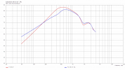
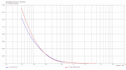
Although the OB speaker produces 6dB less on-axis sound pressure level, the excursion at 50Hz is 25% higher than the CB version (which may be due to the lack of damping effect on the cone excursion by the air sealed in the CB cabinet).
3. Why U- and H-Frame?
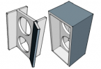
For the reproduction of low frequencies with good sensitivity you need large baffles. Folding the baffle reduces the width of the baffle front and allows a tolerable sensitivity at low frequencies.
The air enclosed in the U- and H-frame designs increases the mass to be moved by the driver and thus lowers the resonant frequency.
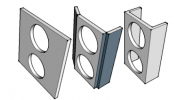
This design reduces the risk of freaking out husbands, who have to limit the width of their newly to be purchased LED TV because of the OB speakers in the living room.
When using a U-frame, the path length is no longer the same at 90°, so the dipole radiation becomes asymmetrical and has more of a hypercardioid shape.

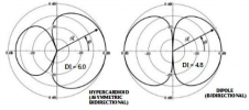
The use of H-frame designs avoids this asymmetry.
Sources:
4. The U-Frame pitfall
The following is not a revelation, but is known to everyone who is somewhat involved with U-Frame OB speaker (as I said before OB is not my expertise, so don't expect jaw-dropping news).
It's just to show you what happens if one uses U-frame (and to some extend H-frame) designs without basic knowledge and what this means for the speaker radiation.
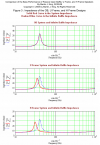
The enclosed air volume in U-frame and H-frame designs naturally begins to resonate, which is an undesirable effect.
As a very rough approximation, one can imagine the designs, according to Martin J. King, as lambda/4 resonators (transmission line) - some kind of "pseudo-lambda/4" resonator.
However, the effective air column does not end abruptly at the edge of the cabinet, but protrudes slightly beyond it.

This characteristic can lead to very unpleasant side effects.
Example 1
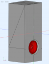
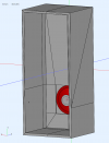
The baffle and driver is almost the same as our reference example in section one. The height is slightly lower at 85cm, but the depth is enormous at 40cm U-frame.
The commercially available loudspeaker (there are probably versions with one or two 15'' woofers instead of one 10'' woofer as in the simulation), plays together with a compression driver horn. So the crossover frequency of the woofer is probably at 800-1200Hz.
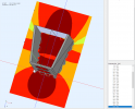
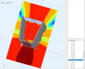
The images are,
- Front and back view of the simulated LS with reference axis as blue line,
- SPL speaker (red) and woofer front (blue) and back (pink) sound separately in 2m distance,
- Horizontal on-axis normalized sonogram,
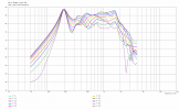
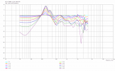
- Horizontal normalized frequency responses 0-90° (10° steps):
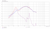
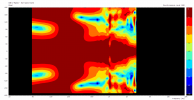
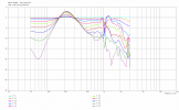
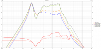
The frequency response is very wavy and therefore difficult to smooth with a passive XO.
The woofer shows acardioid dipole radiation only clearly below 100Hz. Therefore the crossover frequency should not be higher.
Using the woofer up to 800Hz is a clear mistake and shows a much worse radiation than any monopole, because it is extremely uneven.
Example 2
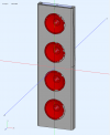
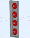
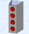
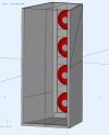
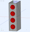
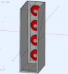
The overall loudspeaker is described by the manufacturer as the "pinnacle of open baffle loudspeaker designs". We will only look at the low bass part of the speaker, which consists of four 6.5'' woofers. The dimensions were roughly estimated for the simulation (minor differences have no effect on the general result).
The dimensions for the simulation with height, width, depth are 85cmx25cmx40cm (33''x10''x16'').
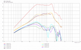
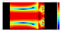
The images are,
- Front and back view of the simulated LS with reference axis as blue line,
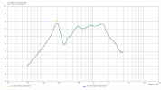
- SPL speaker (red) in 2m distance, topmost woofer is number four ... down to woofer one.
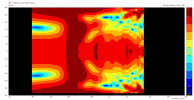
- Horizontal on-axis normalized sonogram,
- Horizontal normalized frequency responses 0-90° (10° steps):
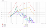
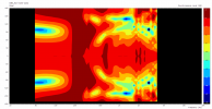
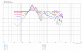
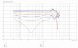
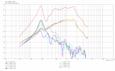
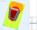
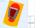
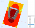
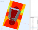
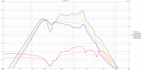
Again, you get a very wavy FR. The "pseudo-lambda/4" resonance of the U-frame causes the sound radiated from the rear to become so dominant that it far exceeds the sound radiated from the front of the drivers (the U-frame "acts" like a monopole because of its dominance in SPL). This widens the radiation extremely and completely destroys all the advantages of a dipole - the reduced lateral radiation.
In this case, the crossover frequency should not exceed 100-150Hz, otherwise the sound pressure level of the lateral frequency responses in the range 180-400Hz can be above that of the on-axis FR and the speaker does not show dipole behavior.
5. H-frame the U-frame killer
When you first think about it, you ask yourself "Huh? How can twice as many "resonance chambers" improve the problem?". The basic problem of the resonance frequency range does not disappear, the resonances still have in and out oscillation (just like any BR concept for example) which will show in the decay behavior.
In section 4 it was pointed out that H-frame concepts have a symmetrical radiation behavior, this of course also applies to the resulting resonances, which thus maintain thecardioid dipole radiation.
Example 3
The simulated speaker is identical to example 2, except that the 40cm cabinet depth uses an H-frame design, rather than the U-frame.
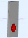
The front and back view of the simulated LS with reference axis as blue line:
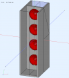
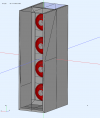
The two "resonator chambers" of the H-frame design are each only 20cm deep, which shifts the "pseudo-lambda/4" resonant frequency to higher frequencies, compared to the U-frame.
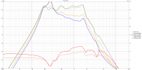
When comparing on-axis frequency response of the U-frame with the H-frame design, the difference is not dramatic. Compared to the classic OB design from example 0, both FR are wavy.
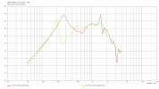
The advantages of the H-frame design becomes obvious when looking at the sound radiation from the front and rear of each driver, as well as the normalized FR.
The images are,
- SPL speaker (red) in 2m distance, topmost woofer is number four ... down to woofer one
- Horizontal on-axis normalized sonogram,
- Horizontal normalized frequency responses 0-90° (10° steps):
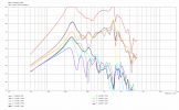
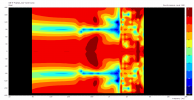
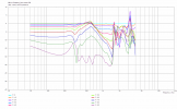
Up to 250Hz crossover frequency the use is possible without radiation problems. If one accepts minor radiation errors, even use up to 500Hz is possible.
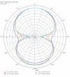
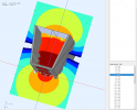
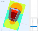
To compare the dramatic differences in the radiation of U-frame and H-frame side by side, here are the 50, 100, 200 and 400Hz polar diagrams (normalized to the axial frequency response) of example 2 and 3:
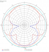
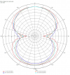
With the U-frame, the radiation above 100Hz is no longer a dipole, but more or less a mess.
The H-frame design shows a relatively even cardioid dipole radiation up to 400Hz.
6. classic flat OB, U-frame or H-frame Design - OB low bass output?
Using example 2, 3 and a classic flat OB version, it will be shown how the low frequency sound pressure level is affected by the different OB design concepts.
The reason for using U/H-frame design, as mentioned above, is to increase the low bass sound pressure level compared to a classic flat OB baffle.
This requires a simulation of example 2 as a classic OB speaker with a flat baffle.
Since I exceed the maximum limit of 35 images per post, this simulation is available in a separate post that can be found here as example 4.
Now we can compare the on-axis SPL of the different concepts (classic flat OB, U-frame 40cm, H-frame 40cm with always the same front baffle):
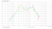
What immediately catches the eye is the very even frequency response of the version with classic flat baffle.
With the choice of the U-frame, the manufacturer of the speaker from example 2 has already made the wrong choice in terms of the radiation of the speaker (if the crossover frequency of the 6.5'' woofer is above 100-150Hz).
Was it at least the right decision to use the U-frame in terms of low frequency sound pressure level output?
For this purpose, the on-axis frequency responses are normalized to the FR of example 2, the U-frame concept chosen by the manufacturer:
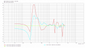
If we look at the low frequency range below 150Hz, the H-frame concept is the better choice there as well, around 100Hz we expect over 1dB and around 50Hz almost 2dB higher sensitivity. Unfortunately, the manufacturer also made the wrong choice in terms of low bass output by choosing a U-frame concept (assuming my simulations do not contain errors).
When using an H-frame concept, compared to the classic flat OB baffle in the low bass range (in this case) around 4dB higher sound pressure can be achieved.
7. V-frame instead of U-frame - what's the difference?
Since I exceed the maximum limit of 35 images per post, see post#13 for this section.
8. H frame with angled side walls
For details see post#31.
9. U-frame resonance side effects
For details see post#32.
When using or purchasing U-frame or V-frame (and to some degree H-frame) dipole designs, there is a risk that design errors will be made by DIY beginners if the necessary basic knowledge is lacking or speakers are purchased which are faulty designs.
Therefore, simple examples will be used to point this out and help you to avoid these pitfalls.
The examples are based on commercially available speakers. Unfortunate some manufacturers sell faulty designs based on U-frame dipole speakers too.
This is very bitter for the paying customers.
BUT if such a desgin error is made, it does not mean that the entire speaker will sound bad - please keep this in mind for the further sections.
I am not an expert on dipole design of loudspeakers, detailed information on dipole speakers can be found at Siegfried Linkwitz's website.
Before discussing the pitfalls of U/V-Frame (and to some extend H-frame) design, some basic thoughts on OB speaker.
Index
1. classic OB speaker
2. OB speaker - displacement volume is everything
3. Why U- and H-Frame?
4. The U-Frame pitfall
5. H-frame the U-frame killer
6. classic flat OB, U-frame or H-frame Design - OB low bass output?
7. V-frame instead of U-frame - what's the difference?
8. H frame with angled side walls
9. U-frame resonance side effects
1. classic OB speaker
First, let's look at a classic OB design - so we have a reference to compare to. That means a large flat baffle combined with a driver that can move as much air volume as possible.
Example 0
Here the simulation of an OB baffle with height, width, depth of 100cm x 44cm x 7cm (39''x17''x2.8'') with a 10'' woofer - better would be 18'', but for our comparisons this doesn't matter.
The images are,
- Front and back view of the simulated LS with reference axis as blue line,
- SPL speaker (red) and woofer front (blue) and back (pink) sound separately in 2m distance,
- Horizontal on-axis normalized sonogram,
- Horizontal normalized frequency responses 0-90° (10° steps):


The reference example baffle is not ideally flat, but has a very slight U-frame shape to stay as close as possible to real designs (that use this practice to stabilize the baffle).
2. OB speaker - displacement volume is everything
Would like to list it here for the sake of completeness.
If the wavelength is large compared to the baffle, then the frequency response drops by 6dB/oct (compared to a monopole speaker) due to mutual cancellation of front and rear sound.
The consequences have been described by S. Linkwitz:
Source: https://www.linkwitzlab.com/models.htm#A1"The comparable monopole has a flat frequency response (0 dB), whereas the dipole rolls off at 6 dB/oct. To maintain constant sound pressure level (0 dB) the monopole displaces four times (+12 dB/oct) the air volume for every halving of frequency, but the dipole has to have eight times (+18 dB/oct) the displacement. Very quickly the maximum excursion capability of a driver becomes the limiting factor for maximally achievable sound level. Multiple drivers must be used to go beyond this limit."
The larger the baffle, the later this transition occurs.
The sound pressure curve is of course individually different and depends on the baffle and driver size and the TSP values of the driver.
As an example, a simulation of a loudspeaker, with the same baffle and driver, once as an open baffle design and once as a closed box loudspeaker (CB) design.
More details can be found here ("Analysis" of cardioid speaker radiation via lateral slots) in section four.
In the example shown, the baffle still has an influence on the on-axis frequency responses of the OB and CB versions shown.
The tendency is nevertheless clearly recognizable, the CB speaker drops to low frequencies with about 6dB/oct, but the OB speaker with 10dB/oct. At 50Hz the sound pressure difference is about 6dB in favor of the CB version.


Although the OB speaker produces 6dB less on-axis sound pressure level, the excursion at 50Hz is 25% higher than the CB version (which may be due to the lack of damping effect on the cone excursion by the air sealed in the CB cabinet).
3. Why U- and H-Frame?
For the reproduction of low frequencies with good sensitivity you need large baffles. Folding the baffle reduces the width of the baffle front and allows a tolerable sensitivity at low frequencies.
The air enclosed in the U- and H-frame designs increases the mass to be moved by the driver and thus lowers the resonant frequency.


This design reduces the risk of freaking out husbands, who have to limit the width of their newly to be purchased LED TV because of the OB speakers in the living room.
When using a U-frame, the path length is no longer the same at 90°, so the dipole radiation becomes asymmetrical and has more of a hypercardioid shape.

The use of H-frame designs avoids this asymmetry.

Sources:
4. The U-Frame pitfall
The following is not a revelation, but is known to everyone who is somewhat involved with U-Frame OB speaker (as I said before OB is not my expertise, so don't expect jaw-dropping news).
It's just to show you what happens if one uses U-frame (and to some extend H-frame) designs without basic knowledge and what this means for the speaker radiation.
The enclosed air volume in U-frame and H-frame designs naturally begins to resonate, which is an undesirable effect.
As a very rough approximation, one can imagine the designs, according to Martin J. King, as lambda/4 resonators (transmission line) - some kind of "pseudo-lambda/4" resonator.
However, the effective air column does not end abruptly at the edge of the cabinet, but protrudes slightly beyond it.
This characteristic can lead to very unpleasant side effects.
Example 1
The baffle and driver is almost the same as our reference example in section one. The height is slightly lower at 85cm, but the depth is enormous at 40cm U-frame.
The commercially available loudspeaker (there are probably versions with one or two 15'' woofers instead of one 10'' woofer as in the simulation), plays together with a compression driver horn. So the crossover frequency of the woofer is probably at 800-1200Hz.
The images are,
- Front and back view of the simulated LS with reference axis as blue line,
- SPL speaker (red) and woofer front (blue) and back (pink) sound separately in 2m distance,
- Horizontal on-axis normalized sonogram,
- Horizontal normalized frequency responses 0-90° (10° steps):


The frequency response is very wavy and therefore difficult to smooth with a passive XO.
The woofer shows a
Using the woofer up to 800Hz is a clear mistake and shows a much worse radiation than any monopole, because it is extremely uneven.
Example 2
The overall loudspeaker is described by the manufacturer as the "pinnacle of open baffle loudspeaker designs". We will only look at the low bass part of the speaker, which consists of four 6.5'' woofers. The dimensions were roughly estimated for the simulation (minor differences have no effect on the general result).
The dimensions for the simulation with height, width, depth are 85cmx25cmx40cm (33''x10''x16'').
The images are,
- Front and back view of the simulated LS with reference axis as blue line,
- SPL speaker (red) in 2m distance, topmost woofer is number four ... down to woofer one.
- Horizontal on-axis normalized sonogram,
- Horizontal normalized frequency responses 0-90° (10° steps):


Again, you get a very wavy FR. The "pseudo-lambda/4" resonance of the U-frame causes the sound radiated from the rear to become so dominant that it far exceeds the sound radiated from the front of the drivers (the U-frame "acts" like a monopole because of its dominance in SPL). This widens the radiation extremely and completely destroys all the advantages of a dipole - the reduced lateral radiation.
In this case, the crossover frequency should not exceed 100-150Hz, otherwise the sound pressure level of the lateral frequency responses in the range 180-400Hz can be above that of the on-axis FR and the speaker does not show dipole behavior.
5. H-frame the U-frame killer
When you first think about it, you ask yourself "Huh? How can twice as many "resonance chambers" improve the problem?". The basic problem of the resonance frequency range does not disappear, the resonances still have in and out oscillation (just like any BR concept for example) which will show in the decay behavior.
In section 4 it was pointed out that H-frame concepts have a symmetrical radiation behavior, this of course also applies to the resulting resonances, which thus maintain the
Example 3
The simulated speaker is identical to example 2, except that the 40cm cabinet depth uses an H-frame design, rather than the U-frame.
The front and back view of the simulated LS with reference axis as blue line:


The two "resonator chambers" of the H-frame design are each only 20cm deep, which shifts the "pseudo-lambda/4" resonant frequency to higher frequencies, compared to the U-frame.
When comparing on-axis frequency response of the U-frame with the H-frame design, the difference is not dramatic. Compared to the classic OB design from example 0, both FR are wavy.

The advantages of the H-frame design becomes obvious when looking at the sound radiation from the front and rear of each driver, as well as the normalized FR.
The images are,
- SPL speaker (red) in 2m distance, topmost woofer is number four ... down to woofer one
- Horizontal on-axis normalized sonogram,
- Horizontal normalized frequency responses 0-90° (10° steps):


Up to 250Hz crossover frequency the use is possible without radiation problems. If one accepts minor radiation errors, even use up to 500Hz is possible.
To compare the dramatic differences in the radiation of U-frame and H-frame side by side, here are the 50, 100, 200 and 400Hz polar diagrams (normalized to the axial frequency response) of example 2 and 3:


With the U-frame, the radiation above 100Hz is no longer a dipole, but more or less a mess.
The H-frame design shows a relatively even
6. classic flat OB, U-frame or H-frame Design - OB low bass output?
Using example 2, 3 and a classic flat OB version, it will be shown how the low frequency sound pressure level is affected by the different OB design concepts.
The reason for using U/H-frame design, as mentioned above, is to increase the low bass sound pressure level compared to a classic flat OB baffle.
This requires a simulation of example 2 as a classic OB speaker with a flat baffle.
Since I exceed the maximum limit of 35 images per post, this simulation is available in a separate post that can be found here as example 4.
Now we can compare the on-axis SPL of the different concepts (classic flat OB, U-frame 40cm, H-frame 40cm with always the same front baffle):

What immediately catches the eye is the very even frequency response of the version with classic flat baffle.
With the choice of the U-frame, the manufacturer of the speaker from example 2 has already made the wrong choice in terms of the radiation of the speaker (if the crossover frequency of the 6.5'' woofer is above 100-150Hz).
Was it at least the right decision to use the U-frame in terms of low frequency sound pressure level output?
For this purpose, the on-axis frequency responses are normalized to the FR of example 2, the U-frame concept chosen by the manufacturer:

If we look at the low frequency range below 150Hz, the H-frame concept is the better choice there as well, around 100Hz we expect over 1dB and around 50Hz almost 2dB higher sensitivity. Unfortunately, the manufacturer also made the wrong choice in terms of low bass output by choosing a U-frame concept (assuming my simulations do not contain errors).
When using an H-frame concept, compared to the classic flat OB baffle in the low bass range (in this case) around 4dB higher sound pressure can be achieved.
7. V-frame instead of U-frame - what's the difference?
Since I exceed the maximum limit of 35 images per post, see post#13 for this section.
8. H frame with angled side walls
For details see post#31.
9. U-frame resonance side effects
For details see post#32.
Last edited:

