restorer-john
Grand Contributor
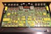
After a couple of stupid but serious mistakes of mine
Pinouts on the TO-92s...

After a couple of stupid but serious mistakes of mine
Oh no. But the VAS transistor physical placement on the PCB is reversed against schematics (it was better re PCB tracks) - I was lazy and modified one of the older PCB designs to keep big tranies position because of existing drills in the heatsink. But I was not careful on parts soldering, placed parts by memory and swapped NPN and PNP VAS parts. Horribly high PSU current, but rail test setup current limiting resistors saved it and nothing went to fire and no part failure except for one of the rail test setup protective resistors. 2 x 58V rails are a lot.Pinouts on the TO-92s...
")
You might like the 20kHz 4ohm power
Love it. 20kHz full power test is necessary for any amplifier on my bench. Square wave looks good- that's 20Vpp into 4R too?
Nothing wrong with the 8 bit scope- you can always turn on averaging/persist to clean it up. Is that the UNI-T PC software? Sure, a CRO looks better, but I have to take a picture with a camera, whereas the Rigol has the screen capture utility and control software. I really only like the DSOs for automatic measurements, zooming in and finding runt/glitches. For everything else, I still use my old skool CRO. They sit side by side. I used to have my old Trio 60MHz on top but sent it to the storeroom. I miss it sometimes.
261W! So your rails are dropping about 10V under full load. One transformer for each channel?
If it's a rainy weekend, I'm going to finish the L-85V restoration and post up some performance figures if I finish it before Monday. I've got some noisy differential front end transistors, so I may be going through the bag and matching up on the curve tracer.
Only that he put it into the Luxman case.
For me, I love the perfect restoration and I only make modifications where there were flaws/faults/reliability issues etc. I have so many amplifiers that it is not the search for the perfect one, but which one to play with today.
But @sabristol has done a great job on what was probably just a fun project amp for him. A long term project for sure. Most likely the original boards got hacked-up or charred-up back in the day and got separated from the amp (ask me how I know things get separated and 'lost').
I think he's done a excellent job and I really like your new design too. Have you ever done designs where you rectify the secondary twice, once for the main OPTs and drivers and a full wave and filter capacitance for the front end/VAS? Off the same main HV secondaries, not a separate higher voltage tapping. Sony called it 'spontaneous twin drive'.
) is that you love restoration of old units and I sincerely hate it and put the thing into dust bin if it no longer works . On the other hand, I love circuit hints and try to tune them and build and verify, like Brabus, you know .That's pretty good!Yes I did, of course that higher supplies for VAS make higher usable output power, just take care of overdriving.
The only difference between us (re electronics
This is the 56Vpeak-peak 4ohm 19+20kHz CCIF measurement on the new amp, the test that @amirm doesn't like to use
View attachment 119077
Still a lot of workbench tests ahead of me.
This is the 56Vpeak-peak 4ohm 19+20kHz CCIF measurement on the new amp
I wanted a portable 2 channel arbitrary waveform generator with reasonable performance for quick tests. I figured this little UNI-T962E at 60MHz/200MSa/S and a 14 bit vertical resolution might be OK. Was not expecting DDS sines to be low THD, but I was surprised.