gamerpaddy
Member
Ive been working on the PA5 for a while now after mine died suddently,
like many others

 www.audiosciencereview.com
Most of the PA5 units develop a crackling, hissing or just go a little silent or completely dead on one or both channels.
This issue is related to the potted D01 module.
Its potting compound expands and contracts when it heats/cools and rips off components in the process.
See my teardown and analysis of it in the PA5 thread here

 www.audiosciencereview.com
After some kind ASR member donated a broken PA5 to me for research purposes, i went on an reverse engineered the D01 module.
My intention was to make a replacement module for anyone to build / buy so their PA5 will live again, and hopefully forever.
Its PCB and Schematic files are open source, and anyone who wants their PA5 fixed without dealing with the support or is out of warranty for drilling holes into it... can just order those at their favourite pcb house and even let them assemble it for you.
So ive started by depotting the module, which i did on my previous unit aswell and its now been running fine ever since. longer than before.
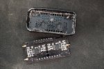
and after stripping & measuring all components, i sanded down the 4 layer PCB
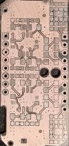
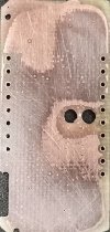
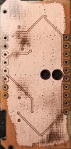
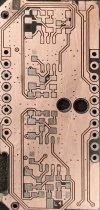
after that, i reversed the schematic from it.

(ignore mute sw L/R, i suspect its mute but could be a floating ground, havent looked into it yet)
And made & ordered some PCB's
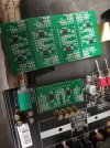
After assembling the other side and testing them, they worked flawlessly.
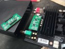
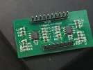
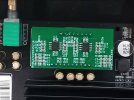
They work, they sound good. Its a worthy replacement for the original Part which will last much longer.
instead of OPA1612 i used OPA1656 since they were in stock and not too expensive, they are very good too, i dont hear any difference.
i cranked the volume to max with nothing playing and didnt hear any hiss / hum.
and i got no way to measure the SINAD of it unfourtainly.
I will not Sell these myself. But i made the design open source so anyone can order pre-assembled PCB's at the usual chinese PCB makers.
The Project can be found here:
Just click on "Editor Open" on the top right.
i havent chosen specific parts for resistors and capacitors in the Bill of materials, when you order them you gotta select your own.
Because sometimes the ones ive chosen are not available 3 months later anymore and you gotta find suiteable parts anyways.
Some component values are weird, just select the ones that are the closest, it doesnt have to be exact. topping used some parts in series to get there like 3x3.3k instead of 10k..
There will be a few versions of this module, mainly focussing on putting every component ontop so Assembly gets way cheaper than both-sided, also DIP8 sockets for those opamp swappers out there. but overall it will stay the same.
just dont pot the module in epoxy or tar.. we've been there. it really doesnt need to be thermally equalized..
Also you dont need a metal shield around it. the D01 metal case is just for looks, it isnt actually connected to Ground for shielding.
edit:
the module i assembled for testing uses slightly different values and opa1656 instead of opa1612 as mentioned, i noticed it having less gain. the original one had its earbleeding volume at about 2/3, this one i can crank to 100% i also noticed a bit tighter bass, at least im seeing the cones move a little more than before.. or im just cranking it further for some reason.
i used 10k instead of 9.9k, 6.8k instead of 6.99k, 1.2k instead of 1.21k, 200 instead of 205ohms and so on.
like many others

Poll for Topping PA5 owners only please.
Poll for PA5 owners to report product defects. Discussion for any solutions. I think it would be useful to get a handle on some numbers to estimate just how wide spread the issues are. Addendum: Here is Topping's response to the PA5 issues...
 www.audiosciencereview.com
Most of the PA5 units develop a crackling, hissing or just go a little silent or completely dead on one or both channels.
This issue is related to the potted D01 module.
Its potting compound expands and contracts when it heats/cools and rips off components in the process.
See my teardown and analysis of it in the PA5 thread here

Topping PA5 Review (Amplifier)
how loud will pa5 drive the hifiman susvara, the actual sensitivity is 79 db/ unknown 1 vrms or not No-one can answer that without the /missing info. Id suggest contacting susvara to ask them.
 www.audiosciencereview.com
After some kind ASR member donated a broken PA5 to me for research purposes, i went on an reverse engineered the D01 module.
My intention was to make a replacement module for anyone to build / buy so their PA5 will live again, and hopefully forever.
Its PCB and Schematic files are open source, and anyone who wants their PA5 fixed without dealing with the support or is out of warranty for drilling holes into it... can just order those at their favourite pcb house and even let them assemble it for you.
So ive started by depotting the module, which i did on my previous unit aswell and its now been running fine ever since. longer than before.

and after stripping & measuring all components, i sanded down the 4 layer PCB


after that, i reversed the schematic from it.
(ignore mute sw L/R, i suspect its mute but could be a floating ground, havent looked into it yet)
And made & ordered some PCB's

After assembling the other side and testing them, they worked flawlessly.


They work, they sound good. Its a worthy replacement for the original Part which will last much longer.
instead of OPA1612 i used OPA1656 since they were in stock and not too expensive, they are very good too, i dont hear any difference.
i cranked the volume to max with nothing playing and didnt hear any hiss / hum.
and i got no way to measure the SINAD of it unfourtainly.
I will not Sell these myself. But i made the design open source so anyone can order pre-assembled PCB's at the usual chinese PCB makers.
The Project can be found here:
Topping PA5 Repair Module / D01 Replacement - EasyEDA open source hardware lab
In EasyEDA open source hardware lab, open source square pools all kinds of electrical design engineerings together to realize resource sharing easily.
oshwlab.com
i havent chosen specific parts for resistors and capacitors in the Bill of materials, when you order them you gotta select your own.
Because sometimes the ones ive chosen are not available 3 months later anymore and you gotta find suiteable parts anyways.
Some component values are weird, just select the ones that are the closest, it doesnt have to be exact. topping used some parts in series to get there like 3x3.3k instead of 10k..
There will be a few versions of this module, mainly focussing on putting every component ontop so Assembly gets way cheaper than both-sided, also DIP8 sockets for those opamp swappers out there. but overall it will stay the same.
just dont pot the module in epoxy or tar.. we've been there. it really doesnt need to be thermally equalized..
Also you dont need a metal shield around it. the D01 metal case is just for looks, it isnt actually connected to Ground for shielding.
edit:
the module i assembled for testing uses slightly different values and opa1656 instead of opa1612 as mentioned, i noticed it having less gain. the original one had its earbleeding volume at about 2/3, this one i can crank to 100% i also noticed a bit tighter bass, at least im seeing the cones move a little more than before.. or im just cranking it further for some reason.
i used 10k instead of 9.9k, 6.8k instead of 6.99k, 1.2k instead of 1.21k, 200 instead of 205ohms and so on.
Last edited:
