• WANTED: Happy members who like to discuss audio and other topics related to our interest. Desire to learn and share knowledge of science required. There are many reviews of audio hardware and expert members to help answer your questions. Click here to have your audio equipment measured for free!

Stereophile has started calculating EPDR.

Travis

Senior Member
Joined
Jul 9, 2018
Messages
455
Likes
552
Not i
Read the thread. The link is in the 4th post. You need to buy the paper to get the formula.

Martin
Not if you are a member of AES.
 

Travis

Senior Member
Joined
Jul 9, 2018
Messages
455
Likes
552
Hi Everyone,

I sent this to MZKM yesterday but just noticed this thread today. Please see attached. You can skip everything and jump to the last equation showing the formula for calculating EPDR from impedance magnitude and impedance phase magnitude.

Just a note of caution that the EPDR derivation is based on a class-B output stage so it's valid for typical class-AB amps but certainly not for class-A and probably has only marginal relevance for class-D amps (would love to hear from a class-D expert on this topic).

For your background, the Benjamin Eric paper includes a thorough analysis of how to relate the speaker load to the amplifier dissipation but it's actually Keith Howard himself who invented EPDR as a cleaner way to present the data. I don't think that Keith has ever published the final calculation so when I came to want to do this myself I had to re-do the derivation and check with Keith that it matched his calculation.

The PDF is from my raw notes and was never intended for publication. It's a bit rough but seems like there's enough interest to justify me posting in this form.

Kind regards,
Jack.
Glad they’re people like you who can grind things like this out. Also reassure me that supporting STEM is worthwhile.

I’m kindda at the “is there an app for that” level.
 

fpitas

Master Contributor
Forum Donor
Joined
Jul 7, 2022
Messages
9,885
Likes
14,213
Location
Northern Virginia, USA

All this was clear from Eric Benjamin's aforementioned AES article, but the message seems not to have filtered through in the 13 years since (footnote 5). Loudspeaker impedance continues to be assessed by considering modulus and phase separately when, as Benjamin showed, there is a much better way to reflect the load's severity from the amplifier's viewpoint. What he did—as Douglas Self did later (footnote 6), though by the less elegant means of SPICE circuit simulation rather than mathematical analysis—was to plot peak output-stage power dissipation vs frequency with respect to a stated resistive load. Benjamin chose 4 ohms as his reference, while Self preferred 8 ohms. Such curves can be calculated analytically from conventional modulus and phase data—no additional measurements are necessary.
 

Alice of Old Vincennes

Major Contributor
Joined
Apr 5, 2019
Messages
1,428
Likes
921
On that note, is there a calculation for how much wattage a wiring gauge can handle for a certain length & impedance? I don’t see it often for residential audio but I see people in car audio always seeing you need Xawg for Y wattage. All I know is a chart showing the wattage loss per length & impedance.
Just use 12 gauge.
 

valerianf

Addicted to Fun and Learning
Joined
Dec 15, 2019
Messages
704
Likes
458
Location
Los Angeles
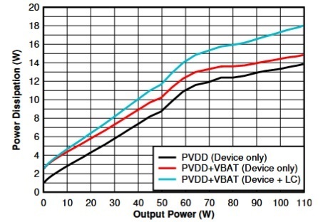
Let us take an example of a class D amp power dissipation with a load of 4 Ohms.
uf21.jpg

For 100W at the output the class D amplifier will dissipated a little more than 17W (blue curve).
To that we need to add the dissipation (11.7W) of the power supply itself that can have an efficiency of 90% if well designed.
In total the class D amplifier+power supply will dissipate 28.7W for 100W delivered on 4 Ohms.
Some nice heat-sink will be needed to reach a good reliability at high sound level.

Here is the link to the reference paper from TI (page 4).
https://www.ti.com/lit/an/slaa996a/...32974&ref_url=https%3A%2F%2Fduckduckgo.com%2F
 

Head_Unit

Major Contributor
Forum Donor
Joined
Aug 27, 2018
Messages
1,364
Likes
722
In total the class D amplifier+power supply will dissipate 28.7W for 100W delivered on 4 Ohms.
Nice post! A far cry from impression of super efficiency that has been promoted/marketed for Class D.
- How representative is this specific example for Class D overall?
- What happens at 8 ohms?
- And at lower wattages?
 

ninanina

Member
Joined
Aug 28, 2023
Messages
12
Likes
3
I recently measured the FOSI V3:

index.php
I recently measured the FOSI V3:

index.php
Magnepan quotes that a high current amp is required to drive Maggies. My simple test to see if a particular amp is ‘high current’ is whether the amps output doubles for a 4 ohm load…ie. If an amps output is 100w into an 8 ohm load and it doubles to 200w into a 4 ohm load it’s considered ‘high current’

The NAD you mentioned states 160w into 8 ohm and 300w into 4 ohm.. ok not quite double but close enough

I use a Mark Levinson No. 383 integrated to drive my Maggie MG.7’s. Quoted specs for the 383 are: 100w into 8 ohms and 200w (minimum) into 4 ohms

Even so the volume control has to be turned up quite high to drive the Maggies. I’ve just added a DWM bass panel to the mix which adds additional load…

Maggies simply soak up the power of any amp!
 

antcollinet

Master Contributor
Forum Donor
Joined
Sep 4, 2021
Messages
7,755
Likes
13,095
Location
UK/Cheshire
How DOES complex impedance related to heat dissipation in class D amps?
It makes little difference because the output devices aren't operating in the linear mode.


Simplistic explanation :
This is all about the energy stored in the equivalent capacitance/inductance of the load which results in the large phase shift. This energy must be supplied by the amp while being stored, and absorbed by the amp when being released. With a Class A or AB amp, that extra energy is absorbed by the output devices as extra dissipation.

With a class D amp, the energy is passed back through the ouput stage into the PSU. The only consequence for class D is that the PSU must have enough capacitance to absorb the energy. There is little extra power loss (only the losses resulting from the current passing through the on state resistance of the output devices) Effectively for class D the reactive energy is passed back and forth between the load reactance, and the PSU capacitance.
 

Head_Unit

Major Contributor
Forum Donor
Joined
Aug 27, 2018
Messages
1,364
Likes
722
whether the amps output doubles for a 4 ohm load
Of course, that usually just means the 8Ω power is underrated, for instance the 100W/200W ohm probably clips at like 133W/200W.* And as we see in this informative thread
https://www.audiosciencereview.com/...ing-a-complex-load-by-power-amplifiers.43900/
started by @pma there's much more to amps than driving resistors. However at least if the manufacturer rates at 4Ω and better yet 2Ω it shows some confidence in ability to drive those low impedance loads, and it's the only information we usually have.

I'd always thought it was Martin Logan that wanted high current, due to the vaguely capacitor nature of their electrostatic panels. The Magnepan LRS for instance has a pretty benign impedance. I suppose this varies by model, and if I were to be cynical I'd say that the thought process of the company pushing towards high current amps might be "the high current amps tend to be the expensive "good stuff" so if we say that's necessary customers will pair our speakers with really good amps instead of some weak thing."

*I've only seen like 3 amps that actually doubled power at clipping...I think a CH Precision is one? And this:
https://www.stereophile.com/content/ps-audio-stellar-m700-monoblock-power-amplifier-measurements
 

Head_Unit

Major Contributor
Forum Donor
Joined
Aug 27, 2018
Messages
1,364
Likes
722
On that note, is there a calculation for how much wattage a wiring gauge can handle for a certain length & impedance? I don’t see it often for residential audio but I see people in car audio always seeing you need Xawg for Y wattage.
I think you are inadvertently conflating something else. Having worked many years in auto engineering, that discussion is usually about what wire gauge is needed from the battery to the amp not from amp to speaker. I was about to say you don't have to worry about it on the speaker side but let's see...
- Pumping 1000W continuous into a subwoofer, a pretty extreme case, into 4Ω would mean
--> P=I^2 * R (power = current squared times resistance)
--> 1000 = I^2 * 4
--> I = sqrt (4000) = 20 amperes if I did that right.
https://www.powerstream.com/Wire_Size.htm would say you need about AWG 9, and AWG12 could get you like 400W @4Ω...but then this chart quite differs, maybe not really showing quite the same thing
https://www.electricaltechnology.or...gauge-awg-chart-wire-size-ampacity-table.html
it seems the AWG 12 would be OK at the 1000W. I'd think you would not really be hitting 1000W continuous even into a loud sub but a clipped one quite possibly (???)
 

peng

Master Contributor
Forum Donor
Joined
May 12, 2019
Messages
5,735
Likes
5,310
*I've only seen like 3 amps that actually doubled power at clipping...I think a CH Precision is one? And this:
https://www.stereophile.com/content/ps-audio-stellar-m700-monoblock-power-amplifier-measurements
Agreed, and how many of those 3 tested for any longer than seconds, or just a couple minutes at best, when loaded with a 4 ohm resistor? I don't have use for "continuous" literally meaning indefinite, just making the point that this double down talks are myth talks, it is not a good guideline for assessing amp's so called "high current" capability, without the details of how it is measured.
 

antcollinet

Master Contributor
Forum Donor
Joined
Sep 4, 2021
Messages
7,755
Likes
13,095
Location
UK/Cheshire
- Pumping 1000W continuous into a subwoofer, a pretty extreme case, into 4Ω would mean
--> P=I^2 * R (power = current squared times resistance)
--> 1000 = I^2 * 4
--> I = sqrt (4000) = 20 amperes if I did that right.
You didn't :)

You have to divide both sides by 4 to get I^2 on it's own.

So I^2 = 1000/4 (Not * 4)

So I = sqrt (250) = 15.8A

(I'm also not sure where you get sqrt of 4000 = 20, it would have been 63.2A.
 

antcollinet

Master Contributor
Forum Donor
Joined
Sep 4, 2021
Messages
7,755
Likes
13,095
Location
UK/Cheshire
On that note, is there a calculation for how much wattage a wiring gauge can handle for a certain length & impedance? I don’t see it often for residential audio but I see people in car audio always seeing you need Xawg for Y wattage. All I know is a chart showing the wattage loss per length & impedance.
The AWG of a wire (or mm squared in EU) determine how much current a wire can carry rather than how much power. The voltage multiplied by the current then determines the power.

In car audio applications the supply is normally only 12V - which means for a given power you need a much higher current, which is why consideration of wire size is more important in car applications.
 
D

Deleted member 48726

Guest
It makes little difference because the output devices aren't operating in the linear mode.


Simplistic explanation :
This is all about the energy stored in the equivalent capacitance/inductance of the load which results in the large phase shift. This energy must be supplied by the amp while being stored, and absorbed by the amp when being released. With a Class A or AB amp, that extra energy is absorbed by the output devices as extra dissipation.

With a class D amp, the energy is passed back through the ouput stage into the PSU. The only consequence for class D is that the PSU must have enough capacitance to absorb the energy. There is little extra power loss (only the losses resulting from the current passing through the on state resistance of the output devices) Effectively for class D the reactive energy is passed back and forth between the load reactance, and the PSU capacitance.
So this is why EPDR isn't relevant for class D amplifiers, right?
 
Top Bottom