• WANTED: Happy members who like to discuss audio and other topics related to our interest. Desire to learn and share knowledge of science required. There are many reviews of audio hardware and expert members to help answer your questions. Click here to have your audio equipment measured for free!

Can output impedance measurement/plot be added to the amplifier test repertoire?

Bob from Florida

Major Contributor
Joined
Aug 20, 2020
Messages
1,307
Likes
1,199
DF verification of how "good" is "good enough" would be an excellent candidate for blind testing. Pick an easy load speaker - relatively flat impedance plot - and a difficult load speaker - not so flat impedance plot and run blind testing with a Benchmark amp with and without a series resistor on the output. That should settle the question of what is good enough for easy and difficult speakers.
 

pma

Major Contributor
Joined
Feb 23, 2019
Messages
4,603
Likes
10,773
Location
Prague
True for the consumer, but the speaker designers will want the information. I know I would.
Even if the information would be a nonsense? And I can make you sure that in case of extremely low numbers it would always be a nonsesnse.
 

egellings

Major Contributor
Joined
Feb 6, 2020
Messages
4,076
Likes
3,320
There are a couple of other threads also. Actually I'm deeply sceptic in one of them I believe. -Where people where explaining to me the factors that drops the DF from high to low in any system. It started with me hearing some difference in amplifier swapping that got me on the wrong track believing the difference was due to the DF being 300 rather than 190. I've since been reading the subject and am convinced that it can't matter because of cables, passive crossover circuits and driver/cabinet equivalent behaviour.

I'll dig out the threads during the day. I believe I have them bookmarked.
Again, once DF is a bit over 20 or 30, with most speakers, increases in that parameter will not be audible.
 

fpitas

Master Contributor
Forum Donor
Joined
Jul 7, 2022
Messages
9,885
Likes
14,212
Location
Northern Virginia, USA
Even if the information would be a nonsense? And I can make you sure that in case of extremely low numbers it would always be a nonsesnse.
i would certainly want to know what I'm designing into a product.
 

fpitas

Master Contributor
Forum Donor
Joined
Jul 7, 2022
Messages
9,885
Likes
14,212
Location
Northern Virginia, USA

mhardy6647

Grand Contributor
Joined
Dec 12, 2019
Messages
11,405
Likes
24,758
The version I heard featured a spherical chicken. Much more bucolic ;)
Spherical cow, in my case... heard the joke from a rather renowned biophysical chemist in my grad school days. Who says scientists don't have a sense of humor? :)
 

fpitas

Master Contributor
Forum Donor
Joined
Jul 7, 2022
Messages
9,885
Likes
14,212
Location
Northern Virginia, USA
Spherical cow, in my case... heard the joke from a rather renowned biophysical chemist in my grad school days. Who says scientists don't have a sense of humor? :)
A radially symmetric sense of humor.
 

Sokel

Master Contributor
Joined
Sep 8, 2021
Messages
6,123
Likes
6,202
Ok,I checked and asked around,the measurement with AP is automated,etc,easy from the software part.
BUT it needs a series of lab grade checks and conditions,so it's time consuming and for no apparent reason as some experts here said.
So,no need,Amir has enough to do already.
 
OP
M

mike7877

Addicted to Fun and Learning
Joined
Aug 5, 2021
Messages
698
Likes
140
Ok,I checked and asked around,the measurement with AP is automated,etc,easy from the software part.
BUT it needs a series of lab grade checks and conditions,so it's time consuming and for no apparent reason as some experts here said.
So,no need,Amir has enough to do already.

Even if it's +- 5% without using lab grade gear (it'd probably be 1), the info would still be useful.

Interesting that you think an amplifier's output impedance is a useless metric - this thread contains many examples of how it's important. Personally I find it interesting how crossover points are shifted. This affects phase and driver integration - causes suck-outs or peaks at crossover points. It doesn't take a big impedance increase for this to make an audible difference. It's one of the reasons that using 8 gauge wire for 6-8 foot runs in 100-200 watt systems is a good idea. Sure, yes, 16 gauge gets most of the power there, but 8 gets it through the crossover and all the way to the drivers properly.

(The less "good" a system is, the less output impedance matters. But that's true of any specification.)

We strive for the best, and an amp with an increased output impedance has a detrimental effect on everything after it in the chain
 
Last edited:
OP
M

mike7877

Addicted to Fun and Learning
Joined
Aug 5, 2021
Messages
698
Likes
140
Amir, what are your thoughts on including output impedance of speaker amps?
 

Sokel

Master Contributor
Joined
Sep 8, 2021
Messages
6,123
Likes
6,202
Even if it's +- 5% without using lab grade gear (which it would be), the info would still be useful.

Interesting that you think an amplifier's output impedance is a useless metric.

This thread contains many examples of how it's important. You could read the thread!

(The less "good" a system is, the less it matters. But that's true of any specification
I don't think it's useless on the contrary,only the fact that it's contained in the AP's suite of measurements tells me that is useful.
I only pointed the fact of time,which in Amir's case can be translated to more reviews or on another more real-life-like metric,like the latest complex impedance measurement for example.

Edit:It's also relatively easy to get those measurements,a lot of the new amps include it in their data sheets.That's both of mine for example:

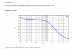
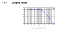
1200as2.PNG300a2.PNG
 
Last edited:
OP
M

mike7877

Addicted to Fun and Learning
Joined
Aug 5, 2021
Messages
698
Likes
140
I don't think it's useless on the contrary,only the fact that it's contained in the AP's suite of measurements tells me that is useful.
I only pointed the fact of time,which in Amir's case can be translated to more reviews or on another more real-life-like metric,like the latest complex impedance measurement for example.

Edit:It's also relatively easy to get those measurements,a lot of the new amps include it in their data sheets.That's both of mine for example:

View attachment 291849View attachment 291850

Although it's included by the manufacturers, so are a lot of other things which, time and time again, we see aren't accurate (premise for this site)

Also, an added 20-30 seconds on amplifier reviews won't take away from other reviews...
Say Amir does 3 reviews one day. Shaving 30 seconds off of one won't let him squeeze in 4
 

Sokel

Master Contributor
Joined
Sep 8, 2021
Messages
6,123
Likes
6,202
Although it's included by the manufacturers, so are a lot of other things which, time and time again, we see aren't accurate (premise for this site)

Also, an added 20-30 seconds on amplifier reviews won't take away from other reviews...
Say Amir does 3 reviews one day. Shaving 30 seconds off of one won't let him squeeze in 4
Agreed on the bold,depends of the intended market I suppose.
As long as icePower measurements is a pro audio thing so lying would not be a good idea.

Where accuracy suffers greatly thought is usually in power output vs frequency for example,or the duration of it (mostly peak,that's hard).
I would like more of that,whole spectrum ones,in some cases (active biamping for example) can come very handy.
 
OP
M

mike7877

Addicted to Fun and Learning
Joined
Aug 5, 2021
Messages
698
Likes
140
Agreed on the bold,depends of the intended market I suppose.
As long as icePower measurements is a pro audio thing so lying would not be a good idea.

Where accuracy suffers greatly thought is usually in power output vs frequency for example,or the duration of it (mostly peak,that's hard).
I would like more of that,whole spectrum ones,in some cases (active biamping for example) can come very handy.

I'd prefer it over the whole spectrum as well. That seems harder to implement though. But who knows - once something is set up, it's literally the press of a button. This time a second step: the dummy load.

Is it already done this way for headphone amps?

Measuring the voltage drop at a couple hundred points during a frequency sweep and plotting that (after calculation applied that gives output impedance obv)

Edit: what do you mean power output vs frequency: higher power + higher frequency?
 

Sokel

Master Contributor
Joined
Sep 8, 2021
Messages
6,123
Likes
6,202
Edit: what do you mean power output vs frequency: higher power + higher frequency?
Example:

index.php


That's my cap of tea in measurements.Or SINAD vs level,helps calculate real world scenarios were attenuation is a necessary evil (no one listen to 0db across all the devices).
 

solderdude

Grand Contributor
Joined
Jul 21, 2018
Messages
16,054
Likes
36,441
Location
The Neitherlands
Is it already done this way for headphone amps?

Headphone amps usually have a very constant output R over the audible frequency range.
Some (the ones with a coupling cap) may see an increase in output R in the lowest frequencies and an inconsequential rise for higher frequencies (overall gain/feedback related) or an output transformer (tube amps).
Amir measured it at 1kHz I believe. The first measurements were incorrect anyway as the test cable/setup seemed to skew the results.

For headphone amps the output R seems to be in the range between 0ohm and several hundred ohm.
 
OP
M

mike7877

Addicted to Fun and Learning
Joined
Aug 5, 2021
Messages
698
Likes
140
Example:


That's my cap of tea in measurements.Or SINAD vs level,helps calculate real world scenarios were attenuation is a necessary evil (no one listen to 0db across all the devices).

That's exactly what I thought you were referring to.

I've always wondered... say you've got 20W 500Hz sine wave (12.65V 8Ω), and on top of that you've got 1W 15kHz sine wave (2.83v 8Ω).

Does the part of the 15kHz sine wave when it's between 2.83V have THD+n of -98dB, with distortion increasing to -78dB (or so) at the crests of the 500Hz sine wave?

I'd really like to set up the software used here to play around with. I've got a decent audio interface with 4 channels in, 4 out, made by RME. The Babyface Pro. When I chose the device, I was focused on mobile recording, so instead of buying the ADI-2 Pro (which, retrospectively would've been the better buy, as I can count on one hand all of the times I couldn't have used the ADI-2 Pro (I since bought a nice 300W sine wave inverter and a collection of differently sized 12V AGM batteries lol))

The Babyface Pro FS was reviewed here. The RME website specs THD+n of its ADC as -108dB, and Amir's measurement of it is -107.83 and -107.81 - IMO identical. The ADI-2 FS was also reviewed here, measured as -115dB THD+n. RME's website specifies -114dB for unbalanced, -116 XLR. So, although I haven't come across any 3rd party measurements of my non-FS version of the Babyface Pro, because RME seem to be accurate and even sometimes generous with the measurements they give of their products, I believe the -104dB THD+n spec given. In the mixer console, the peak meter has the level in dB at the top of each channel, and for the XLR inputs the level given is -105. This is in line with specs given, as, at one point I sent -6dB to the input and it registered properly.

Anyway... you seem to know a bit about the software. Is it free to use for personal use? Free trial? -104dB THD+n is definitely good enough to measure almost anything as long as it isn't [proper] hi-fi or professional equipment. I've got good balanced and RCA cables with excellent ends and can avoid pesky ground loops by running my machine with the 300W sine wave inverter (or laptop). If I get it going I've got a few items I know people here would be interested in knowing the specs of. I also have a couple friends with some similarly interesting items I could borrow
 
Top Bottom