If the Amp is flat into the speaker it has low enough output impedance for that speaker. (I dont know if Amir does that, it would take a complex load, and then what kind?) Or, Vout=A times Vin at all frequncies, which is all an amp is supposed to do. Easy to measure, if you know the load.Not necessarily just bass. Most real world crossovers make for a wavy, goofy response.

-
WANTED: Happy members who like to discuss audio and other topics related to our interest. Desire to learn and share knowledge of science required. There are many reviews of audio hardware and expert members to help answer your questions. Click here to have your audio equipment measured for free!
You are using an out of date browser. It may not display this or other websites correctly.
You should upgrade or use an alternative browser.
You should upgrade or use an alternative browser.
Can output impedance measurement/plot be added to the amplifier test repertoire?
- Thread starter mike7877
- Start date
No the effect is the difference between the green line and the red one (the 8Ω to 4Ω change) not the drop at 20k from band limiting. So its less than .1db?I think that is enough data. For example Topping PA5:
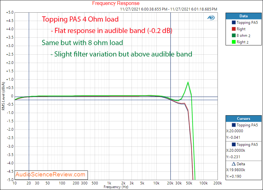
It's not flat and varies by load. This suggests non-flat output impedance. The effect is -0.23 dB for selected loads at 20 kHz, which is all I want to know about it with this amplifier.
If you want more, go ahead and ask Amir")
This is exactly the measurement you need for output impedance.
mhardy6647
Grand Contributor
- Joined
- Dec 12, 2019
- Messages
- 11,405
- Likes
- 24,758
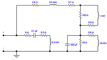
Well... there's the Ken Kantor/Stereophile simulated loudspeaker load.If the Amp is flat into the speaker it has low enough output impedance for that speaker. (I dont know if Amir does that, it would take a complex load, and then what kind?) Or, Vout=A times Vin at all frequncies, which is all an amp is supposed to do. Easy to measure, if you know the load.
Real-Life Measurements Page 2
However, the rising impedance above 5kHz, coupled with a positive phase angle---intended, I assume, to be equivalent to the tweeter voice-coil inductance---is almost never found in a real speaker. I modified the Kantor circuit by adding a Zobel network---a resistor and capacitor in...
 www.stereophile.com

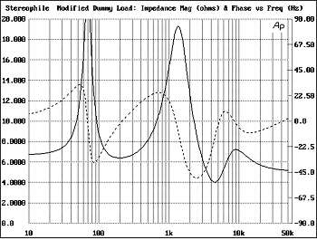
(modified from Ken Kantor's design to add a Zobel for treble impedance compensation)
PS (and apropos of nothing
) Ken Kantor's (still) pretty active as a photographer: 

D
Deleted member 48726
Guest
What is the dB variation from your example here?Even if it's +- 5% without using lab grade gear (it'd probably be 1), the info would still be useful.
Interesting that you think an amplifier's output impedance is a useless metric - this thread contains many examples of how it's important. Personally I find it interesting how crossover points are shifted. This affects phase and driver integration - causes suck-outs or peaks at crossover points. It doesn't take a big impedance increase for this to make an audible difference. It's one of the reasons that using 8 gauge wire for 6-8 foot runs in 100-200 watt systems is a good idea. Sure, yes, 16 gauge gets most of the power there, but 8 gets it through the crossover and all the way to the drivers properly.
(The less "good" a system is, the less output impedance matters. But that's true of any specification.)
We strive for the best, and an amp with an increased output impedance has a detrimental effect on everything after it in the chain
KSTR
Major Contributor
We should not neglect the effect of power compression in the speaker itself because that's the elephant in the room here. When VC's heat up and become higher DC resistance this has a much larger impact on everything than a change of source impedance from zero to, say, 0.2Ohms. Copper has a tempco of 0.4%/K. So a 25K temperature change causes a 10% VC resistance increase.Even if it's +- 5% without using lab grade gear (it'd probably be 1), the info would still be useful.
Interesting that you think an amplifier's output impedance is a useless metric - this thread contains many examples of how it's important. Personally I find it interesting how crossover points are shifted. This affects phase and driver integration - causes suck-outs or peaks at crossover points. It doesn't take a big impedance increase for this to make an audible difference. It's one of the reasons that using 8 gauge wire for 6-8 foot runs in 100-200 watt systems is a good idea. Sure, yes, 16 gauge gets most of the power there, but 8 gets it through the crossover and all the way to the drivers properly.
(The less "good" a system is, the less output impedance matters. But that's true of any specification.)
We strive for the best, and an amp with an increased output impedance has a detrimental effect on everything after it in the chain
Sokel
Master Contributor
- Joined
- Sep 8, 2021
- Messages
- 6,128
- Likes
- 6,206
That's Amir's measurement there,AP's software and hardware are no free neither cheap.That's exactly what I thought you were referring to.
I've always wondered... say you've got 20W 500Hz sine wave (12.65V 8Ω), and on top of that you've got 1W 15kHz sine wave (2.83v 8Ω).
Does the part of the 15kHz sine wave when it's between 2.83V have THD+n of -98dB, with distortion increasing to -78dB (or so) at the crests of the 500Hz sine wave?
I'd really like to set up the software used here to play around with. I've got a decent audio interface with 4 channels in, 4 out, made by RME. The Babyface Pro. When I chose the device, I was focused on mobile recording, so instead of buying the ADI-2 Pro (which, retrospectively would've been the better buy, as I can count on one hand all of the times I couldn't have used the ADI-2 Pro (I since bought a nice 300W sine wave inverter and a collection of differently sized 12V AGM batteries lol))
The Babyface Pro FS was reviewed here. The RME website specs THD+n of its ADC as -108dB, and Amir's measurement of it is -107.83 and -107.81 - IMO identical. The ADI-2 FS was also reviewed here, measured as -115dB THD+n. RME's website specifies -114dB for unbalanced, -116 XLR. So, although I haven't come across any 3rd party measurements of my non-FS version of the Babyface Pro, because RME seem to be accurate and even sometimes generous with the measurements they give of their products, I believe the -104dB THD+n spec given. In the mixer console, the peak meter has the level in dB at the top of each channel, and for the XLR inputs the level given is -105. This is in line with specs given, as, at one point I sent -6dB to the input and it registered properly.
Anyway... you seem to know a bit about the software. Is it free to use for personal use? Free trial? -104dB THD+n is definitely good enough to measure almost anything as long as it isn't [proper] hi-fi or professional equipment. I've got good balanced and RCA cables with excellent ends and can avoid pesky ground loops by running my machine with the 300W sine wave inverter (or laptop). If I get it going I've got a few items I know people here would be interested in knowing the specs of. I also have a couple friends with some similarly interesting items I could borrow
For my (newbie) measurements I use Multitone Analyzer which is amazing,you can do just about everything (even construct signals like the one you described).
There's also a thread about it here,the author @pkane is super helpful.

Beta Test: Multitone Loopback Analyzer software
This is a software beta-test for IMD and THD aficionados with an intense desire for multi-tone audio testing :) The start of the documentation and the download website is here: https://distortaudio.org/multitone.html (for 64-bit Windows) Multi-tone Analyzer (MA) was more of an experiment than...
www.audiosciencereview.com
- Thread Starter
- #147
We should not neglect the effect of power compression in the speaker itself because that's the elephant in the room here. When VC's heat up and become higher DC resistance this has a much larger impact on everything than a change of source impedance from zero to, say, 0.2Ohms. Copper has a tempco of 0.4%/K. So a 25K temperature change causes a 10% VC resistance increase.
Wow that's a higher coefficient than I thought!
I don't think it's as big of a deal as you think though.
I've gone through it before, I'll go through some figures with my ATC SCM20 Pro PSL Mk2 speakers:
(although the woofer has a similar appearance to the SCM20s reviewed here. Since then there have been so many changes, that the woofer's similar appearance is the only thing similar that the 25 year old (likely somewhat broken) example has in common with my most recent ATC SCM20 Pro PSL Mk2
They call it a 150mm (6") driver, but the diameter of the cone + 1/3rd of the surround is 135mm, or 5.31"
It's a beast of a woofer - it's underhung, has an 8mm voice coil in a 20mm gap (travels very close to distortion-free when within its 12mm peak to peak excursion ability, and the magnet, is massive.
Sure it's small, but this could very well be a 10 or 12 inch high fidelity woofer as well - it's equipped, except for the frame (the frame would be bigger and would dissipate heat even better.
OK. So when I bought these speakers, I lived in an apartment. Unfortunately the woofers didn't care that people were around - I still needed to loosen them up. Fortunately I had an idea: play infrasonic tones, and increase the time you play them.
I did.
I put 23Hz through them during the day 40 watts of it. I didn't measure the woofer's impedance at that frequency, so I used 6.8 or something. 40 watts is an estimate, but it's probably within 5 watts or so. Anyway, these woofers, cast basket/frame, are quite heavy. They weigh about 20 pounds.
It took 40 watts and many many (6?) hours for the frame of this woofer (which includes that 5/8" thick part where the screws go through at the front) for the temperature to increase and then taper to 53 degrees Celsius
That's 40 watts RMS.
Music with:
RMS voltage: 0.987
Peak to Peak voltage: 8.12
Into 6.8 ohms:
RMS: 0.143W
Peak to Peak: 1.21W
1.21/0.143 * 40 = 338
It would take music with peaks (kicks) at 340 watts to do this same amount of heating.
The first figures I used after "Music with:" came from a screenshot of my oscilloscope. I was using my Topping G5 to drive the speakers above directly with ZZ Top - I Got the Six. I have them sitting about 5 feet apart, and I was about 4.5 feet away from them. They were playing more than loud enough to enjoy the music. With the door shut and someone in the next room watching TV, they could identify the song over the TV.
Now, let's increase this by 4 times so that RMS is ~0.5W and peak to peak is ~4W
That means we'll get 1/80th of the heat (not exactly, but good enough for my purpose here)
1/80 of 35 degrees is 0.5 degrees (35 degrees comes from the coil being about 5 degrees hotter than the chassis: very likely because of physics, and room temp being 23 degrees: very likely because I keep things at 23)
0.4% of 0.5 is 0.2%
You can only really buy 1% components, so even 2.5WRMS and 20W peak to peak would still be undetectable.
The SCM20 Pro PSL Mk2 speakers use 1% caps and hand wound coils which are exact.
Also, the speaker discussed here is a sealed design, so all of the heat was kept inside the enclosure - a port would've let a lot of air in and out for cooling. And a 10 or 12 inch woofer (more typical candidates for 3" voice coils) would have a lot more surface area for cooling.
My take on it is this: coil heating doesn't have a meaningful effect until the speakers are underpowered or you're playing them too loud.
When you play them too loud, parts do go out of spec, and so do your ears. Don't listen too loud!
lol
- Thread Starter
- #148
That's Amir's measurement there,AP's software and hardware are no free neither cheap.
For my (newbie) measurements I use Multitone Analyzer which is amazing,you can do just about everything (even construct signals like the one you described).
There's also a thread about it here,the author @pkane is super helpful.
Beta Test: Multitone Loopback Analyzer software
This is a software beta-test for IMD and THD aficionados with an intense desire for multi-tone audio testing :) The start of the documentation and the download website is here: https://distortaudio.org/multitone.html (for 64-bit Windows) Multi-tone Analyzer (MA) was more of an experiment than...
I'm downloading and going to play around with that!
- Thread Starter
- #149
That's Amir's measurement there,AP's software and hardware are no free neither cheap.
For my (newbie) measurements I use Multitone Analyzer which is amazing,you can do just about everything (even construct signals like the one you described).
There's also a thread about it here,the author @pkane is super helpful.
Beta Test: Multitone Loopback Analyzer software
This is a software beta-test for IMD and THD aficionados with an intense desire for multi-tone audio testing :) The start of the documentation and the download website is here: https://distortaudio.org/multitone.html (for 64-bit Windows) Multi-tone Analyzer (MA) was more of an experiment than...
I'm going to try testing an old thing I bought - SMSL m100.
I thought I read -100dB THD+n as the spec when I bought it. When it arrived, I knew I was lied to. Too much detail was missing. Now they've got this on the Amazon page:
THD+N: -117dB
RCA output 0.0003%
First of all... 0.0003% isn't -117,
it's 110.
And second...
no.
Just.....
no
My Arcam rDac (RIP) sounded so much better. And its THD+n was -102dB.
I finally got both working through my USB hub (laptop has one port :/
This will be interesting!
- Thread Starter
- #150
That's Amir's measurement there,AP's software and hardware are no free neither cheap.
For my (newbie) measurements I use Multitone Analyzer which is amazing,you can do just about everything (even construct signals like the one you described).
There's also a thread about it here,the author @pkane is super helpful.
Beta Test: Multitone Loopback Analyzer software
This is a software beta-test for IMD and THD aficionados with an intense desire for multi-tone audio testing :) The start of the documentation and the download website is here: https://distortaudio.org/multitone.html (for 64-bit Windows) Multi-tone Analyzer (MA) was more of an experiment than...
(I tested device loopback because I couldn't get the M100 working)
Am I doing something wrong?
I've got some excellent XLR cables going from in to out, but for some reason, in addition to the 1kHz wave, I've also got 895Hz 795Hz, and 590Hz, as well as 1104.2Hz, 1205.9Hz, and 1407.7Hz popping up...
All the actual harmonics are way down where you'd expect, with H3 being -105.
THD is -98dB while SNR is 63. WTH!
I don't want to derail this thread, but do you know what's happening here?
edit: is this jitter? Is it my crappy laptop causing this? Bad USB driver? Bad chipset?
Ugh
Last edited:
Sokel
Master Contributor
- Joined
- Sep 8, 2021
- Messages
- 6,128
- Likes
- 6,206
It's a noise problem,try playing with your grounds.View attachment 291926
(I tested device loopback because I couldn't get the M100 working)
Am I doing something wrong?
I've got some excellent XLR cables going from in to out, but for some reason, in addition to the 1kHz wave, I've also got 895Hz 795Hz, and 590Hz, as well as 1104.2Hz, 1205.9Hz, and 1407.7Hz popping up...
All the actual harmonics are way down where you'd expect, with H3 being -105.
THD is -98dB while SNR is 63. WTH!
I don't want to derail this thread, but do you know what's happening here?
edit: is this jitter? Is it my crappy laptop causing this? Bad USB driver? Bad chipset?
Ugh
Also try ASIO or WASAPI exclusive,shared mode carries all the windows sins with it.
D
Deleted member 48726
Guest
But.. You don't know about the VC temperature? Or did I miss that info?Wow that's a higher coefficient than I thought!
I don't think it's as big of a deal as you think though.
I've gone through it before, I'll go through some figures with my ATC SCM20 Pro PSL Mk2 speakers:
View attachment 291900
View attachment 291901
(although the woofer has a similar appearance to the SCM20s reviewed here. Since then there have been so many changes, that the woofer's similar appearance is the only thing similar that the 25 year old (likely somewhat broken) example has in common with my most recent ATC SCM20 Pro PSL Mk2
They call it a 150mm (6") driver, but the diameter of the cone + 1/3rd of the surround is 135mm, or 5.31"
It's a beast of a woofer - it's underhung, has an 8mm voice coil in a 20mm gap (travels very close to distortion-free when within its 12mm peak to peak excursion ability, and the magnet, is massive.
Sure it's small, but this could very well be a 10 or 12 inch high fidelity woofer as well - it's equipped, except for the frame (the frame would be bigger and would dissipate heat even better.
OK. So when I bought these speakers, I lived in an apartment. Unfortunately the woofers didn't care that people were around - I still needed to loosen them up. Fortunately I had an idea: play infrasonic tones, and increase the time you play them.
I did.
I put 23Hz through them during the day 40 watts of it. I didn't measure the woofer's impedance at that frequency, so I used 6.8 or something. 40 watts is an estimate, but it's probably within 5 watts or so. Anyway, these woofers, cast basket/frame, are quite heavy. They weigh about 20 pounds.
It took 40 watts and many many (6?) hours for the frame of this woofer (which includes that 5/8" thick part where the screws go through at the front) for the temperature to increase and then taper to 53 degrees Celsius
That's 40 watts RMS.
Music with:
RMS voltage: 0.987
Peak to Peak voltage: 8.12
Into 6.8 ohms:
RMS: 0.143W
Peak to Peak: 1.21W
1.21/0.143 * 40 = 338
It would take music with peaks (kicks) at 340 watts to do this same amount of heating.
The first figures I used after "Music with:" came from a screenshot of my oscilloscope. I was using my Topping G5 to drive the speakers above directly with ZZ Top - I Got the Six. I have them sitting about 5 feet apart, and I was about 4.5 feet away from them. They were playing more than loud enough to enjoy the music. With the door shut and someone in the next room watching TV, they could identify the song over the TV.
Now, let's increase this by 4 times so that RMS is ~0.5W and peak to peak is ~4W
That means we'll get 1/80th of the heat (not exactly, but good enough for my purpose here)
1/80 of 35 degrees is 0.5 degrees (35 degrees comes from the coil being about 5 degrees hotter than the chassis: very likely because of physics, and room temp being 23 degrees: very likely because I keep things at 23)
0.4% of 0.5 is 0.2%
You can only really buy 1% components, so even 2.5WRMS and 20W peak to peak would still be undetectable.
The SCM20 Pro PSL Mk2 speakers use 1% caps and hand wound coils which are exact.
Also, the speaker discussed here is a sealed design, so all of the heat was kept inside the enclosure - a port would've let a lot of air in and out for cooling. And a 10 or 12 inch woofer (more typical candidates for 3" voice coils) would have a lot more surface area for cooling.
My take on it is this: coil heating doesn't have a meaningful effect until the speakers are underpowered or you're playing them too loud.
When you play them too loud, parts do go out of spec, and so do your ears. Don't listen too loud!
lol
And you don't know if the increased temperature had an effect on the frequency response because you didn't measure it?
Huh? Show me some numbers, I'm not buying itI find it interesting how crossover points are shifted. This affects phase and driver integration - causes suck-outs or peaks at crossover points. It doesn't take a big impedance increase for this to make an audible difference. It's one of the reasons that using 8 gauge wire for 6-8 foot runs in 100-200 watt systems is a good idea. Sure, yes, 16 gauge gets most of the power there, but 8 gets it through the crossover and all the way to the drivers properly
After some more thought, measuring the difference in Vout (VL) from a 8Ω to a 4Ω load at 1volt output (not sure but full power measurements might introduce other factors like current limiting etc.) and usingWell... there's the Ken Kantor/Stereophile simulated loudspeaker load.
Real-Life Measurements Page 2
However, the rising impedance above 5kHz, coupled with a positive phase angle---intended, I assume, to be equivalent to the tweeter voice-coil inductance---is almost never found in a real speaker. I modified the Kantor circuit by adding a Zobel network---a resistor and capacitor in...
(modified from Ken Kantor's design to add a Zobel for treble impedance compensation)
PS (and apropos of nothing

you can figure out Zs.
- Thread Starter
- #155
Huh? Show me some numbers, I'm not buying it
You come across combative (constructive criticism).
The example you seek is on pages 3-5. Most likely it's on 3 or 4. There's also a small possibility it's at the end of two (though 2 is less likely than 5)
Search pages in this order: 3, 4, 5, 2.
If you're feeling especially lucky, you can switch 4 with 3! Maybe search "uf" or "capac" - I think they'll pull up the post (it's the only post with capacitor math)
- Thread Starter
- #156
But.. You don't know about the VC temperature? Or did I miss that info?
And you don't know if the increased temperature had an effect on the frequency response because you didn't measure it?
"the coil being about 5 degrees hotter than the chassis"
It's an educated guess. If you know a Physician he could confirm
lolol
I'll explain it without him, just rationally: heat transfer from the voice coil to the magnet is extremely efficient. If it wasn't, the 200 watt bass transient every 0.7 seconds vs. 10 grams of copper? after a few beats that copper would be vapor. If not, the VC former would at least be cooked. Even a tweeter - its 0.1g copper getting a 10w cymbal crash? that's the end, too.
This specific woofer also has a much larger voice coil and smaller basket than most woofers, and it's an underhung design, meaning at no time was any of the coil not in extremely close proximity to its heatsink: the magnetic top plate
Last edited:
D
Deleted member 48726
Guest
That's a far far shot below it's actual temperature! You can't guesstimate temperature."the coil being about 5 degrees hotter than the chassis"
It's an educated guess. If you know a Physician he could confirm
lolol
I'll explain it without him, just rationally: heat transfer from the voice coil to the magnet is extremely efficient. If it wasn't, the 200 watt bass transient every 0.7 seconds vs. 10 grams of copper? after a few beats that copper would be vapor. If not, the VC former would at least be cooked. Even a tweeter - its 0.1g copper getting a 10w cymbal crash? that's the end, too.
This specific woofer also has a much larger voice coil and smaller basket than most woofers, and it's an underhung design, meaning at no time was any of the coil not in extremely close proximity to its heatsink: the magnetic top plate
There exists VC tests and actual measurements of temp. I recall the temperature being several 100 deg C. Also compression in FR is measurable.
Because of transients nature (short peak) they can take much more power than you should think. Your intuition is sadly wrong about the physics involved.
As far as I'm concerned your test shows nothing useful so your conclusions are wrong.
The knowledge and theory exists in this forum. I would like to help you find it but I'm busy at the moment and only on the phone.
Last edited by a moderator:
MAB
Major Contributor
Here is a refence on VC temps."the coil being about 5 degrees hotter than the chassis"
It's an educated guess. If you know a Physician he could confirm
lolol
I'll explain it without him, just rationally: heat transfer from the voice coil to the magnet is extremely efficient. If it wasn't, the 200 watt bass transient every 0.7 seconds vs. 10 grams of copper? after a few beats that copper would be vapor. If not, the VC former would at least be cooked. Even a tweeter - its 0.1g copper getting a 10w cymbal crash? that's the end, too.
This specific woofer also has a much larger voice coil and smaller basket than most woofers, and it's an underhung design, meaning at no time was any of the coil not in extremely close proximity to its heatsink: the magnetic top plate
Voice Coil Temperature
The magnet temperatures are over 100C lower. This is an extreme example demonstrating B&O's thermal-compression/limiting DSP, which limits the predicted VC temps to 200C. But the point is the VC gets hot!!!
B&O Tech: Thermal Compression Compensation
#9 in a series of articles about the technology behind Bang & Olufsen loudspeakers Recipe for`Befuddled Speaker Enthusiast´ Makes: One individual with reduced faith in louds…
www.tonmeister.ca
- Thread Starter
- #159
Yeah, that's an extreme case. This is like I described though, 40 watts continuous into a magnet and voice coil sized for a concert... temps are low.Here is a refence on VC temps.
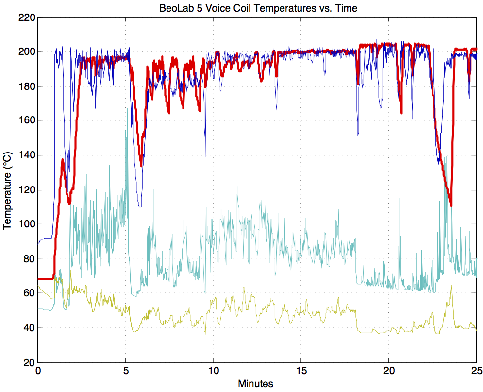
And as @KTSR says, the temperature coefficient is significant and the voice coil gets hot. The Klippel paper points out it is the most important limiter of acoustic output. For instance, here is a graph of BeoLab5 voice coil temps running full volume:Voice Coil Temperature
www.klippel.de
The magnet temperatures are over 100C lower. This is an extreme example demonstrating B&O's thermal-compression/limiting DSP, which limits the predicted VC temps to 200C. But the point is the VC gets hot!!!
B&O Tech: Thermal Compression Compensation
#9 in a series of articles about the technology behind Bang & Olufsen loudspeakers Recipe for`Befuddled Speaker Enthusiast´ Makes: One individual with reduced faith in louds…www.tonmeister.ca
Overhung and underhung heat transfer is very different, too
If those speakers would survive running like that for 6 hours, the magnets would get much hotter. Those are also very likely vented - this hot air had nowhere to go
- Thread Starter
- #160
That's a far far shot below it's actual temperature! You can't guesstimate temperature.
There exists VC tests and actual measurements of temp. I recall the temperature being several 100 deg C. Also compression in FR is measurable.
Because of transients nature (short peak) they can take much more power than you should think. Your intuition is sadly wrong about the physics involved.
As far as I'm concerned your test shows nothing useful so your conclusions are wrong.
The knowledge and theory exists in this forum. I would like to help you find it but I'm busy at the moment and only on the phone.
You got my point backwards....
because the VCs can take the transients while in the magnetic gap, but not outside it (the coils literally become red hot and break almost instantly when they jump the gap) heat transfer is very efficient.
Think about the following:
It's 40 watts into a >200 oz magnet and 3 inch voice coil. If properly vented it could dissipate 300 watts. What temperature would everything be then?
That is, if 40 watts increases the voicecoil temperature from 23 degrees to 58 degrees, 300 watts increases the voicecoil temperature to...
(hint, probably something like that experiment above)
I generally don't make assertions without being right.
I also used an IR thermometer on the edge of the dust cap, where the voice coil former attaches to the cone. This area was a little cooler than the rest of the cast basket
Last edited:
Similar threads
- Replies
- 133
- Views
- 10K
- Replies
- 18
- Views
- 689
- Replies
- 3
- Views
- 360
- Replies
- 37
- Views
- 2K