• WANTED: Happy members who like to discuss audio and other topics related to our interest. Desire to learn and share knowledge of science required. There are many reviews of audio hardware and expert members to help answer your questions. Click here to have your audio equipment measured for free!

Marantz CINEMA 70s AVR - Teardown, personal thoughts and a few measurements

OP
trl

trl

Major Contributor
King of Mods
Joined
Feb 28, 2018
Messages
1,982
Likes
2,556
Location
Iasi, RO
[...] The ADC that you could not identify is obviously hidden below or behind some circuit boards, but based on Denon's, it is likely the AK1803A, that has very similar specs to the one they previously used, the AK5358. [...]

And PCM1803A it is, like you said, hidden under a thicker cable, just near one the PCM5100A chips. :)

IMG_4639.jpg
 

MCH

Major Contributor
Joined
Apr 10, 2021
Messages
2,661
Likes
2,275
Just opened it up again now and checked: between pins 12, 13 and 15 the resistance is higher than zero Ohms, so CLK pins are not paralleled on none of the four PCM5102A DAC chips. Same applies to the other two PCM5100A DAC chips as well, no CLK pins are tied together between chips.
Much appreciated! If the resistance measured was not 0 but in the 100s of Ohms they might still be coming from the same source with some input resistorsin between (?)
 
OP
trl

trl

Major Contributor
King of Mods
Joined
Feb 28, 2018
Messages
1,982
Likes
2,556
Location
Iasi, RO
Only between two DAC chips the resistance was almost 300 Ohms, but for the others was much higher (haven't tried a higher scale, sorry).
 
  • Like
Reactions: MCH

MCH

Major Contributor
Joined
Apr 10, 2021
Messages
2,661
Likes
2,275
Only between two DAC chips the resistance was almost 300 Ohms, but for the others was much higher (haven't tried a higher scale, sorry).
this is exactly what i needed to know. thanks again.
 
OP
trl

trl

Major Contributor
King of Mods
Joined
Feb 28, 2018
Messages
1,982
Likes
2,556
Location
Iasi, RO
[...]​
What surprises me more is that output stage performance degrades that much in Eco mode. At 5 W into 4 R, even the reduced voltage should have plenty headroom. So what is going on? Are the output transistors getting underbiased? Or even worse, are the LTP and VAS getting a lower bias current, too?
Hello, I managed earlier today to measure the bias voltage and it was 5 mV per each channel, pretty much identical on all. As per ONKYO A-9010 service manual, that has the same output stage transistors and recommends 8 mV for biasing, I increased each channel's bias voltage to 8 mV. I've use my multimeter, but later I checked with my PicoScope as well, due to my rather poor resolution for mV measurements to my BRYMEN BM257s.

IMG_4641.jpg

Measuring clips clamped to the two serialised biasing resistors

Per the above and knowing that the emitter resistances are 0.22 Ohms each, then I = U/R = 5mV/440mOhms = 11mA. After bias increase I got 18mA idling current on each channel, which will increase a little bit more idling power consumption and will also warm up the output stage a little bit more (1-2C while idling).

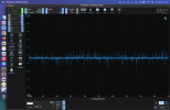
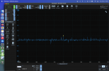
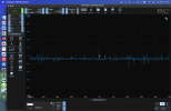
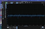
Bias_idling_voltage-ECO_Off-Original copy.jpgBias_idling_voltage-ECO_On-Original copy.pngBias_idling_voltage-ECO_Off-Modded copy.pngBias_idling_voltage-ECO_On-Modded copy.png
Original bias voltage: ECO-Mode OFF 5.2mV, ECO-Mode ON 3.9mV vs. increased bias voltage: ECO-Mode OFF 8.3mV, ECO-Mode ON 4mV


Eco_Mode-OFF.jpg

While idling, but not in stand-by, power consumption in Eco-Mode OFF raised from 27W to 32.6W

ECO_Mode-ON.jpg

While idling, but not in stand-by, power consumption in Eco-Mode ON is about the same as it used to be before increasing the bias current


THD+N_FrontRight_PureDirect_5W-BIAS_8mV.png

@5W/4Ohms, Front Right channel in Pure Direct got an increase in SINAD from 74.7 dB to 79.1 dB

THD+N_SurroundRight_5W-BIAS_8mV.png

@5W/4Ohms, Surround Right channel in Multichannel got an increase in SINAD from 78.5 dB to 81.3 dB

THD+N_FrontRight_MultiCh_5W-BIAS_8mV.png

@5W/4Ohms, Front Right channel in Multichannel got an increase in SINAD from 78.5 dB to 81.7 dB
At 21.5 W I got about the same SINAD results, meaning that increasing the bias current for the output stage has no influence for output power of 20 W and probably neither for above 20 W, suggesting that this AV Receiver is setup to operate around the SINAD of 80 dB for each channel, meaning a THD+N of 0.01%.

After increasing the bias voltage I haven't got time to measure the SINAD with ECO Mode Off, but given that the bias voltage looks pretty much the same as initially I don't think there will be any noticeable difference.
 

Thomas_A

Major Contributor
Forum Donor
Joined
Jun 20, 2019
Messages
3,469
Likes
2,467
Location
Sweden
Nice to see the bias trimming. Not so much SINAD increase though, but good to have it at ≈80 dB. A bit strange that pure direct gave a bit higher THD.
 

martin900

Active Member
Joined
Jan 31, 2020
Messages
160
Likes
183
Not sure what do you mean, could you please elaborate a bit?

I see Su'scon AU series 6800uF/63V @105V caps handling the ripple after the bridge rectifier. These caps are able to support a ripple current of 3.39A RMS and seem to be quite right for the job of smoothing the DC voltage following the bridge rectifier. As per manufacturer wrote:
"Snap-in type 105℃ 2000 hours specially designed for audio equipment
‧Select structural materials with high sound quality
‧Create high definition audio equipment with high sound quality
‧Suitable for high quality audio equipment"
"2000hours,with application of rated Voltage voltage at 105℃".


I also see many Koshin KR-3 caps, probably just fine for general use. In our case I see these caps following linear regulators, but also used as decoupling caps too. Datasheet says: "Guaranteed for 2000 hours at 85°C".

Also, several ELNA caps can be seen as well in audio circuitry.
Given the very high number of electrolytic capacitors from an AV Receiver, I think it would be very pricey to work only with Nichicon and ELNA caps, at least not at the price of the CINEMA 70s. The most stressed caps are the two Su'scon 6800uF/63V from the power supply and the Koshin ones from around the power stage transistors, but time will tell if they'll fail in 5, 10 or more years.

But 30-40 years ago it was not an issue to use A-tier caps like Nippon Chemi-Con, Elna, Panasonic or Nichicon even in lo/mid budget hardware. It's called greedflation - cheaper, faster, more and MFG's need to find a way to make it fail quicker so you'll run to the store to get a new one. Bad quality caps are the easiest way to achieve a short(er) lifespan.
Marantz was known for using A-tier caps most of the time but it looks like this myth has fallen, too.

Electrolytics in lower capacitances are dirt cheap in bulk so it shouldn't even be a consideration for a device costing €1000 (unless they're discounted, seen varying prices).

I know your mileage will vary but after having to recap or discard multiple <10 year old devices and seeing more and more C-tier junk being used even by top mfg's like Marantz just makes me sick and furious at the same time.
 
Last edited:

restorer-john

Grand Contributor
Joined
Mar 1, 2018
Messages
12,743
Likes
38,992
Location
Gold Coast, Queensland, Australia
Hello, I managed earlier today to measure the bias voltage and it was 5 mV per each channel, pretty much identical on all. As per ONKYO A-9010 service manual, that has the same output stage transistors and recommends 8 mV for biasing, I increased each channel's bias voltage to 8 mV. I've use my multimeter, but later I checked with my PicoScope as well, due to my rather poor resolution for mV measurements to my BRYMEN BM257s.

View attachment 337739
Measuring clips clamped to the two serialised biasing resistors

Per the above and knowing that the emitter resistances are 0.22 Ohms each, then I = U/R = 5mV/440mOhms = 11mA. After bias increase I got 18mA idling current on each channel, which will increase a little bit more idling power consumption and will also warm up the output stage a little bit more (1-2C while idling).

View attachment 337735View attachment 337737View attachment 337734View attachment 337736
Original bias voltage: ECO-Mode OFF 5.2mV, ECO-Mode ON 3.9mV vs. increased bias voltage: ECO-Mode OFF 8.3mV, ECO-Mode ON 4mV


View attachment 337728
While idling, but not in stand-by, power consumption in Eco-Mode OFF raised from 27W to 32.6W

View attachment 337729
While idling, but not in stand-by, power consumption in Eco-Mode ON is about the same as it used to be before increasing the bias current


View attachment 337710
@5W/4Ohms, Front Right channel in Pure Direct got an increase in SINAD from 74.7 dB to 79.1 dB

View attachment 337709
@5W/4Ohms, Surround Right channel in Multichannel got an increase in SINAD from 78.5 dB to 81.3 dB

View attachment 337718
@5W/4Ohms, Front Right channel in Multichannel got an increase in SINAD from 78.5 dB to 81.7 dB
At 21.5 W I got about the same SINAD results, meaning that increasing the bias current for the output stage has no influence for output power of 20 W and probably neither for above 20 W, suggesting that this AV Receiver is setup to operate around the SINAD of 80 dB for each channel, meaning a THD+N of 0.01%.

After increasing the bias voltage I haven't got time to measure the SINAD with ECO Mode Off, but given that the bias voltage looks pretty much the same as initially I don't think there will be any noticeable difference.

There is little to no point messing with bias at the levels you were measuring.

Bias is adjusted at low levels, say 250mW- 1W, where you are looking for the crossover notch, particularly the difference between positive and negative switch/glitches in waveform. This already partially shows in your plots where the odd harmonics are affected. At high levels like you measured, the contribution from crossover notch distortion is much less of the overall output.

It’s a poor amplifier stage, no two ways about it. Dodgy Su’scon 6800uF caps for 7 channels rated at 50wpc is an absolute disgrace. That heatsink and supply is not even adequate for 2 channels! It shows the “Marantz” of today is just a shell of a name with nothing in common with quality gear of the past.

Thanks for the ‘teardown’ @trl - I’m sure plenty of people are thankful.
 
OP
trl

trl

Major Contributor
King of Mods
Joined
Feb 28, 2018
Messages
1,982
Likes
2,556
Location
Iasi, RO
But 30-40 years ago it was not an issue to use A-tier caps like Nippon Chemi-Con, Elna, Panasonic or Nichicon even in lo/mid budget hardware. It's called greedflation - cheaper, faster, more and MFG's need to find a way to make it fail quicker so you'll run to the store to get a new one. Bad quality caps are the easiest way to achieve a short(er) lifespan.
Marantz was known for using A-tier caps most of the time but it looks like this myth has fallen, too.
[...]
I don't think 20-30 years ago there were so many capacitor manufacturers to choose from, BTW you forgot about Japanese Rubycon brand that was widely used in most audio electronic equipment. :)

Nowadays there're plenty of low-cost brands capacitors manufacturers that sell similar performance caps (at least on the datasheet, of course) at probably less than half the price.

[...]
It’s a poor amplifier stage, no two ways about it. Dodgy Su’scon 6800uF caps for 7 channels rated at 50wpc is an absolute disgrace. That heatsink and supply is not even adequate for 2 channels! It shows the “Marantz” of today is just a shell of a name with nothing in common with quality gear of the past.
[...]
The ONKYO A-9010, that uses the same output stage transistors, is using SAMWHA 2 x 8200uF/105C (that failed) and this is a stereo amplifier, not a 7 channels one, so indeed installing only 2 x 6800uF might probably work in a 2 x 40 Watts stereo amplifier. Even my 25 years old 2 x 20 Watts Delia/Unitra stereo receiver has 2 x 4700 uF inside, while Yamaha A-S701 has 2 x 12000 uF Nippon Chemi-Con for smoothing the ripple.
 

capslock

Senior Member
Joined
Jun 19, 2020
Messages
339
Likes
153
Thanks for this investigation! So Eco mode decreases output transistor bias current. What else does it decrease? Is the input stage and VAS run off a lower voltage and at decreased current?
 
Last edited:

Thomas_A

Major Contributor
Forum Donor
Joined
Jun 20, 2019
Messages
3,469
Likes
2,467
Location
Sweden
There is little to no point messing with bias at the levels you were measuring.

Bias is adjusted at low levels, say 250mW- 1W, where you are looking for the crossover notch, particularly the difference between positive and negative switch/glitches in waveform. This already partially shows in your plots where the odd harmonics are affected. At high levels like you measured, the contribution from crossover notch distortion is much less of the overall output.

It’s a poor amplifier stage, no two ways about it. Dodgy Su’scon 6800uF caps for 7 channels rated at 50wpc is an absolute disgrace. That heatsink and supply is not even adequate for 2 channels! It shows the “Marantz” of today is just a shell of a name with nothing in common with quality gear of the past.

Thanks for the ‘teardown’ @trl - I’m sure plenty of people are thankful.
Nevertheless, the slim line is a very welcome form factor and I "think" they sell well (now at least at the sub-Euro 700 price). Around -80 dB THD+N @ 5W is enough for audibility limits, especially if you could add on some small good quality amps using L/R pre out and use the other amps for the less critical surround channels. There is a limit what you can push inside such a small cabinet, which of course also limits beefy capacitor banks, large heat sinks and big transformers. I am happy they exist and time will tell when my two small NR series amps will fail, if they do.

Questions regarding performance remain though; @amirm measured ≈10-12 dB worse SINAD, strange ECO mode behaviour and @tlr found more jitter skirts (as found in NR1510/1710) than Amir.
 

Paweł L

Member
Joined
Aug 18, 2021
Messages
99
Likes
46
You also see jitter skirts, which Amir did not using the Toslink input but did so with analog input. The jitter skirts are there in NR1710 as well when the DAC is in the loop. A few more questions then:

Did you test both analog and digital input? (and which one is in your graphs?)
What input level did you use, and what volume setting?

Edit:

And in the case for bias, at least they should be adjusted to be identical for each amp? This is what I have for the NR1710:

View attachment 337161
Wow, really ! 2mV, yeah kind of underbiased it is ;)
 

Thomas_A

Major Contributor
Forum Donor
Joined
Jun 20, 2019
Messages
3,469
Likes
2,467
Location
Sweden
Wow, really ! 2mV, yeah kind of underbiased it is ;)
Yes I agree. But perhaps it is s balance for heat and reliability. It is a small cabinet. Just wonder if 4 mV is ok.
 
OP
trl

trl

Major Contributor
King of Mods
Joined
Feb 28, 2018
Messages
1,982
Likes
2,556
Location
Iasi, RO
Thanks for this investigation! So Eco mode decreases output transistor bias current. What else does it decrease? Is the input stage and VAS run off a lower voltage and at decreased current?
There's an entire paragraph in the first post: https://www.audiosciencereview.com/...rsonal-thoughts-and-a-few-measurements.50743/:

"How is Marantz / Denon achieving such an energy saving with this Eco Mode feature? They added a rather big and powerful relay HF115F / 012-2ZS4A 8A/250VAC on the main board that seems to switch on-the-fly from one winding of the transformer to another one, decreasing the AC voltage that powers the bridge rectifier shown a few paragraphs above. I measured 96.5 VDC on +/- rails of the bridge when Eco Mode is turned OFF and 38.53 VDC with this setting turned ON, an unexpected big difference. What’s important is that turning the Eco Mode OFF is indeed saving a lot of energy."

The decrease in the bias idling current is due to the fact that the output stage power rails are practically cut in half.
 

capslock

Senior Member
Joined
Jun 19, 2020
Messages
339
Likes
153
Yes, I caught that. A well designed bias circuit should keep the bias current constant, but admittedly, reducing the voltage that much will change the whole thermal situation.

Assuming the circuit is really the same as that of the A-9010 posted on page 1 of this thread, the long tailed pair will see a constant current even if the voltage is reduced. The current in the LTP determines the current in the VAS via the collector resistors, so the slew rate of the front end should not change with reduced voltage. One would have to know the value of the resistors to determine the voltages across the transistors. If they get too low, capacitances in the transistors will get higher and more non-linear, which could be the origin of some of the added distortion.

One should not that the A-9010 has severely degenerated LTP and VAS stages, so the loop gain is very low which means it cannot correct for underbiased output transistors or nonlinear drivers very well.
 
Last edited:
  • Like
Reactions: trl
OP
trl

trl

Major Contributor
King of Mods
Joined
Feb 28, 2018
Messages
1,982
Likes
2,556
Location
Iasi, RO
Wow, really ! 2mV, yeah kind of underbiased it is ;)
Marantz/Denon installed test points in there to be easier and safer to adjust the bias voltage; same they did in CINEMA 70s as well (there are seven 3-pins test points there). Each testing point has a couple of 10 KOhms resistors added in series. This way, if someone short-circuit any of those pins, nothing bad will happen, due to the 10 KOhms resistors in series with the emitter resistors from the output transistors.

Test-point.jpg

Test point TP4800 from Marantz NR1506 AVR (similar to other D/M AVRs)


IMG_4418_.jpg

The test points where a relative biasing voltage can be measured in CINEMA 70s.
However, service manual is needed for finding the proper biasing voltage, but like @Thomas D. said, 2 mV might suffice.

So, those 2 mV does not represents the actual biasing voltage across the two serialised emitter resistances, but a value that is directly proportional to the biasing idling voltage. Instead, what I was adjusting was the actual biasing voltage measured across the two emitter resistors from the output transistors, not the voltage across the test points (without having the service manual there's no sense to measure across the testing points, because I don't know for sure what values should be there).
 

capslock

Senior Member
Joined
Jun 19, 2020
Messages
339
Likes
153
Well, your voltmeter usually has an input impedance of 10 MOhms, so the resistors will result in the measured voltage across the test points being 0.2% too small.
 
OP
trl

trl

Major Contributor
King of Mods
Joined
Feb 28, 2018
Messages
1,982
Likes
2,556
Location
Iasi, RO
[...] Assuming the circuit is really the same as that of the A-9010 posted on page 1 of this thread, the long tailed pair will see a constant current even if the voltage is reduced. The current in the LTP determines the current in the VAS via the collector resistors, so the slew rate of the front end should not change with reduced voltage. One would have to know the value of the resistors to determine the voltages across the transistors. If they get too low, capacitances in the transistors will get higher and more non-linear, which could be the origin of some of the added distortion. [...]
I'm sure that technically speaking the schematic can be adjusted in a way that performance to not drop while operating in ECO Mode, but in my case, if the ECO Mode is set to AUTO it will switch from OFF to ON automatically when the volume level gets above 50, which is like 2-3 W/channel. I'm thinking that the entire ECO Mode stage was designed to work at low volumes only. This is a nice to have feature for energy saving during silent evenings or nights; I personally use it for about 90% of the time, when watching TV shows or TV series.
 
  • Like
Reactions: MCH
OP
trl

trl

Major Contributor
King of Mods
Joined
Feb 28, 2018
Messages
1,982
Likes
2,556
Location
Iasi, RO
[...] Questions regarding performance remain though; @amirm measured ≈10-12 dB worse SINAD, strange ECO mode behaviour and @tlr found more jitter skirts (as found in NR1510/1710) than Amir.
The skirts vanish immediately after choosing Direct or Pure Direct modes, so skirts might be an effect of post-processing.
 
Top Bottom