There was this measurement when they were talking about how good the crossover filters were with respect to phase response;
"...and even then couldn't reliably tell where the crossover points were either in frequency or phase response, and that's some achievement"
Well, that's one of those statements...
So the statement must refer to a measurement of the speaker with deactivated FIR filter. Because the first thing to do when using FIR is to eliminate the excess phase caused by the crossover filter.
Or they simply mean that they have set the FIR filters "properly", so that the phase rotation of the crossover filters are no longer recognizable on the phase frequency response with FIR filters (in one specific reference point) - which is not witchcraft nowadays (see last section below).
But with FIR filter deactivated this statement would not be a good thing per se, because when using standard crossover filters (LR2, LR4, BU3,...) the phase frequency response can provide information about filter order and possible crossover frequency - with exotic crossover filters this becomes more difficult and with bungled crossover it will be impossible.
For those who are interested, here are a few more details...
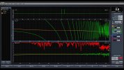
As an example a typical 3-way loudspeaker with Linkwitz-Riley fourth order crossover filter at 400Hz and 3000Hz. If measured correctly (dual channel measurement or similar), you will get something similar to this:

If we would not have the individual measurements of the drivers, only FR (black) and phase frequency response (grey), we could still make some assumptions.
The lowest low frequency range usually behaves like a minimum phase system, therefore the order of the high pass filter (e.g. for CB speaker it would be two) can be derived directly from the frequency response.

In our example, the FR to low frequencies drops by 18dB per octave. This corresponds to a third order filter, i.e. 270° phase rotation (90° phase rotation for each order).
So we mark this phase rotation on the phase frequency response.

In the mid and high frequencies we can see about 2x360° phase rotation, which indicates two fourth order crossover filter. With ideally designed "symmetrical" filters, the crossover frequency would be halfway through the phase rotation.

Note, however, that the filters affect each other, so this is not an exact method, but provides an approximation for the crossover frequencies.
Conversely, you can also start with the high frequencies, then the crossover frequencies correspond exactly to the graphical transitions from +180° to -180° of the phase frequency response in gray - which would give a better match in our case. Normally you would back this with near-field measurements of the drivers.
The German S&R magazine regularly carries out exactly such a analysis in its reviews of active and passive loudspeakers. As an example the KH310 review:

Phase response on axis measured at 2 m distance. At the crossover frequencies of 650 Hz and 2 kHz there is 360° phase rotation each and at the lower end of the transmission range there is another 270° due to the 1st order electrical high pass filter and the 2nd order acoustic high pass filter (closed cabinet).
Source:
S&R magazine
With FIR filters removing the excess phase of the crossover filter, there is not much left to interpret (if you don't have the single driver responses).

Ideally, the phase behaves like a minimum phase system and can be derived directly from the amplitude frequency response.
Update: With FIR filters, of course, the remaining phase frequency response rotation can be linearized - but that would be another topic.


")