I'm holding my horses-
What the baffle dimensions? It may or may not make a measurable or audible difference to go the whole 9 yards, particiarly in a design where costs need to be controlled.
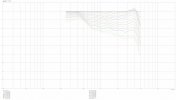
For example, here's the baffle diffraction effect on a 1" dome tweeter on a typical 20cm x 40cm baffle, tweeter 10 cm from the top edge, and centered on the midline.
(1)
View attachment 233966
The green is what would happen on an infinitely large baffle ie. 6dB gain. The blue is what happens to the response instead-
Yikes! Lots of funkiness between about 550Hz up to about 15Khz, with almost up to +/- 3dB between 550Hz and 3Khz.
In a tweeter, where one would have to crossover around ~2.5Khz- this is what creates all kinds of challenges due to the funkiness that changes the on axis (shown) and the off-axis response (not shown, but equally complex).
Here's how it looks now with a 1" roundover:
(2)
View attachment 233967
Ah better, particularly above 6Khz, but still +2/-1dB effects between 550Hz and 3Khz.
(Now a waveguided tweeter, in effect, has it's own concave baffle, so the tweeter is not affected by the flat baffle it's on, thus avoiding the baffle diffraction issue of the lower treble ripple response as seen above. Related to this is the tweeter's output, which has a change in dispersion that closely matches the woofer's dispersion (that's why you want a tweeter on small 5" waveguide when matched with a small 5" mid-woofer and much larger waveguide when matched with a larger 15" midwoofer in a 2 way)
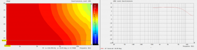
Moving on, here's the same tweeter 10cm from the top of a wider 11" baffle, which is typically what's needed for a 8-10" woofer in a 3 way.
View attachment 233970
Now you're going to say- well it's not as good as a rounded over cabinet! And I agree.
But certainly it's not as atrocious as the initial cabinet with no round-over.
But guess what? In a 3 way you're typically crossing the tweeter to the midrange cone/dome at or above 3KHz,
(3)
View attachment 233971
So the funkiness in the region of interest is +/-1 dB, not +/-3dB.
Here's the same, with just a
1/2" roundover:
(4)
View attachment 233975
So on a 3 way design, for a tweeter on a 11" baffle- the diffraction effects are reduced.
So here are the options:
A) do less baffle edge treatments (graph 4)
B) live with it (graph 3)
So let's be aware of our blind spots: optimal baffle shape and dimensions is but one part of loudspeaker design.
But it depends on what frequencies you're dealing with.
What happens when you put a 3" piston (approximation of a 3" cone or dome on the baffle. You can equalize out the peak around 1Khz.
Can you live with that 1dB dip around 2Khz? Or do you need a cu$tomi$ed waveguide?
View attachment 233976
It's not as "terrible" as you think.... It costs a LOT of money to go with a fully customized diffraction mitigation/adaptation/controlled baffle
ala. Vivid Audio...