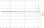
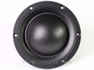
I have been thinking for a long time whether I should try to analyze the speaker project or not.
After the first video with the superlatives and the "we have built this only for ourselves" - rather not. But since the second and third video, now clear commercial intentions are pursued with the speaker project, different standards apply than with a DIY speaker project.
Since there is still little information (that I know of) about the speaker itself, the following statements are based on external sources, and simulations.
1. driver selection
A. woofer
The Dayton RS225 (4 and 8 Ohm) has been in production for ages and is a very good woofer. Flat frequency response, fast decay, good impedance control and very low harmonic distortion - the last two characteristics also because of the two demodulation rings.
B. tweeter
When selecting drivers, many designers make sure that the driver shows a piston like behavior for as long as possible in the range of use, i.e. does not break down into modes and breakup resonances - because these make the behavior of the driver less predictable. One can certainly be divided about the possible tonal effects.
Modes and breakup resonances require settling and decay time and can influence the radiation behavior of the driver.
Sources: HiFiCompass and my own simulations and graphical evaluations
The choice fell on a 25mm Bliesma silk dome - T25S-6. The Blisma tweeters don't have any directivity control setups like a small waveguide and literally consist only of the dome with surround on a flat face plate. This provides a very wide dispersion, leaves many options open to the designer, but means a very intense interaction with the baffle when installed flat.
Due to the "simple" external construction of the Bliesma tweeters, they can be simulated very well. This allows us to easily identify the frequencies up to which the tweeters show ideal pistonic behavior.
Here is the comparison of the Bliesma Be-tweeter with an ideal tweeter (normalized to on-axis FR):
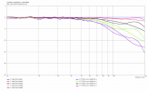
Up to 8kHz the T25B-6 shows ideal piston-like behavior and above 8kHz there are only minor deviations.
Now let's look at the behavior of the T25S-6 used in the speaker (again compared to an ideal tweeter):
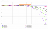
As not unusual for silk domes, a deviation from the ideal behavior can already be observed at frequencies >3kHz. Silk domes often show a "controlled breakup" over a wide frequency range. Above 7kHz and off-axis, the T25S-6 shows significantly more deviations from ideal behavior than the T25B-6 tweeter.
The orange rectangle marks an interesting part. Here the T25S-6 shows a particularly wide radiation (for an already wide radiating tweeter). Even at 6kHz, the SPL of the 45° frequency response measurement is identical to the on-axis level. Harmonic distortion and decay >2kHz are excellent (except for a tiny disturbance around 3kHz).
The T26S-6 would not have been my choice from a technical point of view.
For the simulation shown below, this means that the range 3-6kHz will radiate wider in reality than in the simulation.
C. midrange
The same considerations apply to the midrange driver as to the tweeter - a pistonic behavior over as wide a frequency range as possible and breakup resonances not before above the operating range.
The post is way too long and 50% of the readers already won't make it to this point
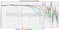
Therefore, only very briefly the comparison of the Be dome M74B-6 with the silk dome M74S-6 which was selected for the speaker:
Sources: HiFiCompass and my own simulations and graphical evaluations
Up to about 5kHz the radiation pattern of Be- and silk dome is almost identical and should be very close to the radiation pattern of an ideal mid-dome (with the same design).
For a silk mid-dome, this is unusually good behavior. If you are not looking for a crossover frequency >4kHz, the M74S-6 is the right choice.
2. radiation and crossover simulation
A. simulation model and limitations
Much of the information had to be awkwardly derived from the video and pictures shown (so there might be deviations from the real speaker here and there) :
speaker cabinet
Depth 150mm
Width 250mm
Height 550mm / 1050mm
Drive positions "half cabinet" (550mm) / normal cabinet (1050mm)
Dayton RS-225-4 210mm / 710mm
Bliesma M74S-6 387mm / 887mm
Bliesma T26S-6 490mm / 990mm
(Mic reference axis) 439mm / 940mm
Volume for woofer about 23L
Anyone who knows the exact dates is welcome to share them.
The crossover frequencies are assumed to be 400Hz/3500Hz (but can be easily changed in the attached VCAD file).
Since no free field measurements were made during the design, no exact statements can be made about the acoustic filter slopes used. For the simulation I chose LR4 (this can also be changed in the attached VCAD file).
To save computing time, I simulated only the upper half of the speaker. For tweeter and midrange this has hardly any effect, for the woofer the changes are also within limits, as a comparison of the baffle diffraction for both versions (545mm versus 1100mm height) shows.
orange=diffraction for small baffle, blue=diffraction for normal baffle
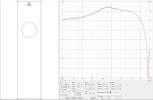
The side edges and the upper edge of the cabinet were rounded with a radius of 10mm.
The simulation is only intended to give a rough overview of the radiation behavior of the speaker.
The BEM model ended up looking like this (note: don't get confused, only the dome/cone and surround are drawn in, not the outer edges of the drivers):
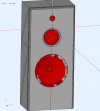
The simulation was created for the range 50Hz-14kHz, everything else should be ignored.
B. simulation and crossover
The simulation results were imported into VCAD, where a crossover was set up with 400/3000Hz LR4 and tuned for smoothly sloping PIR and SP.
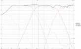
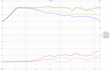
Due to the extremely wide dispersion of mid dome and tweeter above 1.5kHz, strong hor edge diffraction occurs. Therefore, the best way to tune might be to completely ignore the on-axis FR and the LW and concentrate on a smoothly downward sloping PIR and SP.
Since the speakers are not used as nearfield monitors, the wavy on-axis FR and LW should not be too much of a problem.
I have attached the VCAD file, then everyone who is interested can make tests with it (Update: In the example XO crossover frequencies are now 400/3500Hz instead of 400/3000Hz).
C. simulation evaluation
The evaluation is based on an example crossover with crossover frequencies of 400Hz/3500Hz and LR4 filter slopes - with other XO the radiation will of course change somewhat.
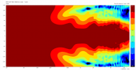
From about 400Hz the slightly wavy DI behaves at a constant level until about 8kHz. Together with the wide dispersion, this means that in normal listening rooms the on-axis FR should probably show a slight downward tilt.
The hor radiation is extremely wide and if you include the information from section 1.B, the radiation around 3-6kHz should be even wider in reality.
hor normalized sonogram, black line is -6dB limit
Why a flat tuning to the on-axis FR or to the LW makes no sense becomes apparent when you look at the hor normalized FR:
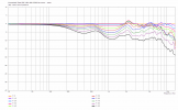
Far too much "high frequency energy" would then be radiated into the room from 1.5kHz and above.
The normalized vertical radiation looks good (with the XO explained above). The wide radiation in the range of 2-8kHz is also apparent here (except in the range around the crossover frequency - obviously).
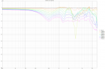
The wide radiation in the range 1.5-8kHz will definitely provide a lot of detail, but must also be kept in check somehow.
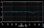
The only measurement we know of the speaker is room measurement at the listening position shown in the video - once before and after equalization.
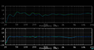
If we look at the equalized frequency response with a common scaling, we can easily see that the frequency range of roughly 2-6kHz was lowered by up to 3dB - in an acoustically treated studio.
Update 2: It was brought to my attention that the M74S-6 has a small waveguide. I changed this in the simulation and also added a 10mm rounding to three edges.
The changes are not dramatic but present, so I have replaced all diagrams and the VCAD project file with the current version.
Update 3: The simulation has been improved thanks to further hints. I hope that the simulation is even closer to reality than it was before. I have replaced all diagrams and the VCAD project file with the new version. The dimensions of the cabinet and the driver positions have also been adjusted and changed in text.
.
After the first video with the superlatives and the "we have built this only for ourselves" - rather not. But since the second and third video, now clear commercial intentions are pursued with the speaker project, different standards apply than with a DIY speaker project.
Since there is still little information (that I know of) about the speaker itself, the following statements are based on external sources, and simulations.
1. driver selection
A. woofer
The Dayton RS225 (4 and 8 Ohm) has been in production for ages and is a very good woofer. Flat frequency response, fast decay, good impedance control and very low harmonic distortion - the last two characteristics also because of the two demodulation rings.
B. tweeter
When selecting drivers, many designers make sure that the driver shows a piston like behavior for as long as possible in the range of use, i.e. does not break down into modes and breakup resonances - because these make the behavior of the driver less predictable. One can certainly be divided about the possible tonal effects.
Modes and breakup resonances require settling and decay time and can influence the radiation behavior of the driver.
Sources: HiFiCompass and my own simulations and graphical evaluations
The choice fell on a 25mm Bliesma silk dome - T25S-6. The Blisma tweeters don't have any directivity control setups like a small waveguide and literally consist only of the dome with surround on a flat face plate. This provides a very wide dispersion, leaves many options open to the designer, but means a very intense interaction with the baffle when installed flat.
Due to the "simple" external construction of the Bliesma tweeters, they can be simulated very well. This allows us to easily identify the frequencies up to which the tweeters show ideal pistonic behavior.
Here is the comparison of the Bliesma Be-tweeter with an ideal tweeter (normalized to on-axis FR):

Up to 8kHz the T25B-6 shows ideal piston-like behavior and above 8kHz there are only minor deviations.
Now let's look at the behavior of the T25S-6 used in the speaker (again compared to an ideal tweeter):

As not unusual for silk domes, a deviation from the ideal behavior can already be observed at frequencies >3kHz. Silk domes often show a "controlled breakup" over a wide frequency range. Above 7kHz and off-axis, the T25S-6 shows significantly more deviations from ideal behavior than the T25B-6 tweeter.
The orange rectangle marks an interesting part. Here the T25S-6 shows a particularly wide radiation (for an already wide radiating tweeter). Even at 6kHz, the SPL of the 45° frequency response measurement is identical to the on-axis level. Harmonic distortion and decay >2kHz are excellent (except for a tiny disturbance around 3kHz).
The T26S-6 would not have been my choice from a technical point of view.
For the simulation shown below, this means that the range 3-6kHz will radiate wider in reality than in the simulation.
C. midrange
The same considerations apply to the midrange driver as to the tweeter - a pistonic behavior over as wide a frequency range as possible and breakup resonances not before above the operating range.
The post is way too long and 50% of the readers already won't make it to this point
Therefore, only very briefly the comparison of the Be dome M74B-6 with the silk dome M74S-6 which was selected for the speaker:

Sources: HiFiCompass and my own simulations and graphical evaluations
Up to about 5kHz the radiation pattern of Be- and silk dome is almost identical and should be very close to the radiation pattern of an ideal mid-dome (with the same design).
For a silk mid-dome, this is unusually good behavior. If you are not looking for a crossover frequency >4kHz, the M74S-6 is the right choice.
2. radiation and crossover simulation
A. simulation model and limitations
Much of the information had to be awkwardly derived from the video and pictures shown (so there might be deviations from the real speaker here and there) :
speaker cabinet
Depth 150mm
Width 250mm
Height 550mm / 1050mm
Drive positions "half cabinet" (550mm) / normal cabinet (1050mm)
Dayton RS-225-4 210mm / 710mm
Bliesma M74S-6 387mm / 887mm
Bliesma T26S-6 490mm / 990mm
(Mic reference axis) 439mm / 940mm
Volume for woofer about 23L
Anyone who knows the exact dates is welcome to share them.
The crossover frequencies are assumed to be 400Hz/3500Hz (but can be easily changed in the attached VCAD file).
Since no free field measurements were made during the design, no exact statements can be made about the acoustic filter slopes used. For the simulation I chose LR4 (this can also be changed in the attached VCAD file).
To save computing time, I simulated only the upper half of the speaker. For tweeter and midrange this has hardly any effect, for the woofer the changes are also within limits, as a comparison of the baffle diffraction for both versions (545mm versus 1100mm height) shows.
orange=diffraction for small baffle, blue=diffraction for normal baffle

The side edges and the upper edge of the cabinet were rounded with a radius of 10mm.
The simulation is only intended to give a rough overview of the radiation behavior of the speaker.
The BEM model ended up looking like this (note: don't get confused, only the dome/cone and surround are drawn in, not the outer edges of the drivers):

The simulation was created for the range 50Hz-14kHz, everything else should be ignored.
B. simulation and crossover
The simulation results were imported into VCAD, where a crossover was set up with 400/3000Hz LR4 and tuned for smoothly sloping PIR and SP.


Due to the extremely wide dispersion of mid dome and tweeter above 1.5kHz, strong hor edge diffraction occurs. Therefore, the best way to tune might be to completely ignore the on-axis FR and the LW and concentrate on a smoothly downward sloping PIR and SP.
Since the speakers are not used as nearfield monitors, the wavy on-axis FR and LW should not be too much of a problem.
I have attached the VCAD file, then everyone who is interested can make tests with it (Update: In the example XO crossover frequencies are now 400/3500Hz instead of 400/3000Hz).
C. simulation evaluation
The evaluation is based on an example crossover with crossover frequencies of 400Hz/3500Hz and LR4 filter slopes - with other XO the radiation will of course change somewhat.
From about 400Hz the slightly wavy DI behaves at a constant level until about 8kHz. Together with the wide dispersion, this means that in normal listening rooms the on-axis FR should probably show a slight downward tilt.
The hor radiation is extremely wide and if you include the information from section 1.B, the radiation around 3-6kHz should be even wider in reality.
hor normalized sonogram, black line is -6dB limit

Why a flat tuning to the on-axis FR or to the LW makes no sense becomes apparent when you look at the hor normalized FR:

Far too much "high frequency energy" would then be radiated into the room from 1.5kHz and above.
The normalized vertical radiation looks good (with the XO explained above). The wide radiation in the range of 2-8kHz is also apparent here (except in the range around the crossover frequency - obviously).

The wide radiation in the range 1.5-8kHz will definitely provide a lot of detail, but must also be kept in check somehow.
The only measurement we know of the speaker is room measurement at the listening position shown in the video - once before and after equalization.

If we look at the equalized frequency response with a common scaling, we can easily see that the frequency range of roughly 2-6kHz was lowered by up to 3dB - in an acoustically treated studio.

Update 2: It was brought to my attention that the M74S-6 has a small waveguide. I changed this in the simulation and also added a 10mm rounding to three edges.
The changes are not dramatic but present, so I have replaced all diagrams and the VCAD project file with the current version.
Update 3: The simulation has been improved thanks to further hints. I hope that the simulation is even closer to reality than it was before. I have replaced all diagrams and the VCAD project file with the new version. The dimensions of the cabinet and the driver positions have also been adjusted and changed in text.
.
Attachments
Last edited:


