• WANTED: Happy members who like to discuss audio and other topics related to our interest. Desire to learn and share knowledge of science required. There are many reviews of audio hardware and expert members to help answer your questions. Click here to have your audio equipment measured for free!

Directiva r1.2 design and build

Rick Sykora

Major Contributor
Forum Donor
Joined
Jan 14, 2020
Messages
3,613
Likes
7,348
Location
Stow, Ohio USA
I think the rabbit must have escaped from the hat ;)

Or perhaps it is a virtual bunny…

more likely the forum software rejected due to txt file content or account rights. @Alan J you may need to package the project into a zip file.
 
OP
A

Alan J

Member
Joined
Jul 14, 2020
Messages
64
Likes
88
Oops. Getting "upload too big." Will try to pare down...
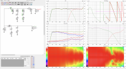
Done - in the post above. Limited resolution in REW export to 48 points per octave (which seems to be what VCAD uses in the merger tool) to get DXT FRs down to a reasonable size.
 
OP
A

Alan J

Member
Joined
Jul 14, 2020
Messages
64
Likes
88
Here's a quickly done passive crossover. I'm not thrilled with the vertical directivity being biased toward the floor which is a matter of which driver slightly leads or lags in the crossover region but that should be addressable. The largest inductor (not an E12 part) would be around 35 ml which is encouraging.

Screenshot 2023-12-05 at 12.38.11 PM.png


Two .vxp files in the attached: The prior no-delays/no-peaks DSP, and the passive. For anyone who looked, sorry about the multiple empty .vxp files in the prior zip!
 

Attachments

  • Directiva1.2dist.zip
    3 MB · Views: 40

Rick Sykora

Major Contributor
Forum Donor
Joined
Jan 14, 2020
Messages
3,613
Likes
7,348
Location
Stow, Ohio USA
Looks pretty nice. Might want to check impedance levels...

Am not experienced with passive crossover design but suspect the design could be much simpler. In active design, adding multiple filters does not have the cost and space penalties of passive. As DIY goes, you get to choose your preferred tradeoffs. So, if you are happy, enjoy!:)
 
OP
A

Alan J

Member
Joined
Jul 14, 2020
Messages
64
Likes
88
Might want to check impedance levels...
Yep. VCAD is showing under 2 ohms and optimization brings it back down even though I have a max impedance specified.

suspect the design could be much simpler.
I agree here as well. When I was playing with passive crossovers for r1, there were some approaches with significantly lower component count, though involving much larger inductors (1-2 mH). But I should probably revisit those topologies. The added (bottom) facets might be helpful, as I'm expecting them to move the baffle step up in frequency a bit and to smooth out the associated hump as well. We shall see!

My goal is to have a volume budget for an internal passive crossover by the time I'm finished with measurements on the prototype box.
 
OP
A

Alan J

Member
Joined
Jul 14, 2020
Messages
64
Likes
88
A parallel notch (in my vernacular, band reject) in place of one of the series notches (in my vernacular, trap filter) tames the impedance significantly and vastly improves power handling. There's a Purifi app note where they do this for similar reasons. Vertical ERDI could be smoother, the design is still pretty "brute force", and now we have some pretty big caps in addition to three inductors of substantial size. But with all that said, I may trudge through the exercise of adding up the volumes of these components.

Screenshot 2023-12-06 at 10.20.21 AM.png

This is version R1 in the attached .vxp.
 

Attachments

  • Passive exploration.vxp.zip
    12.5 KB · Views: 33
Last edited:

Rick Sykora

Major Contributor
Forum Donor
Joined
Jan 14, 2020
Messages
3,613
Likes
7,348
Location
Stow, Ohio USA
Here is my admittedly inexperienced attempt at a passive crossover based on your last project post. Would need more optimizing once you get to measurements on the real speaker. Notably, since your target location is a bookshelf, expect more bass and some adjustments there. Only 7 elements...

1701877661514.png
 
Last edited:

Rick Sykora

Major Contributor
Forum Donor
Joined
Jan 14, 2020
Messages
3,613
Likes
7,348
Location
Stow, Ohio USA
I missed that you went back to the paper woofer. In this case, your design is r1 with a faceted baffle. If you haven’t already, would give the crossovers posted to the Directiva passive crossover thread some serious consideration. There are a couple with better directivity than either of our crossovers are achieving.:cool:
 
OP
A

Alan J

Member
Joined
Jul 14, 2020
Messages
64
Likes
88
A question: Many of the crossovers that have been posted leave a 5 dB or so bump in vertical ERDI, in a 1-2.5 KHz range around the crossover point. Is this a concern? In what I posted above, I was working to avoid it.
 

Rick Sykora

Major Contributor
Forum Donor
Joined
Jan 14, 2020
Messages
3,613
Likes
7,348
Location
Stow, Ohio USA
A question: Many of the crossovers that have been posted leave a 5 dB or so bump in vertical ERDI, in a 1-2.5 KHz range around the crossover point. Is this a concern? In what I posted above, I was working to avoid it.

See this thread...

 
OP
A

Alan J

Member
Joined
Jul 14, 2020
Messages
64
Likes
88
@Rick Sykora - this thread, and the thread on lobing linked there, were helpful. I also got a lot from this tutorial from Sausalito Audio. Happily, there's consistency (+/- full agreement) among the Sausalito tutorial, Kimmo's comments in the threads, and Dennis Murphy's comments.

Anyway, here's my latest iteration. Maybe the crossover point is getting a bit low (driver responses are LR4 2200 for the Purifi and LR4 1900 for the DXT). It tends to drift down with attempt to optimize. This might change with the additional faceting that I'm planning, because that should push the baffle step hump up a bit.

I've had others that mostly eliminate the bump in vertical ERDI, but it's not clear to me that that is a big issue in and of itself. Those designs tend to have even lower crossover frequencies, and/or the two drivers in quadrature rather than in phase, along with hard-to-judge vertical dispersion patterns. Separating the drivers further reduces the hump in vertical ERDI, but the effect is fairly subtle.

The plan:
  • With it being clear that a reasonably sized crossover that I'm happy with is readily within reach, set this part aside.
  • Make some mods to the prototype enclosure: facets at the bottom and probably a modest reduction in depth (now that I have a handle on crossover size and Rg, have confidence that the enclosure is unlikely to need a lot of added structure, and have more confidence in tuning (within reason) with PR mass.
  • Repeat measurements with the modified enclosure.
  • Dig a bit into final enclosure materials. A hot candidate right now is a Corian or equivalent baffle and veneered or cabinet grade plywood rear enclosure.
Screenshot 2023-12-11 at 1.49.01 PM.png
 

Attachments

  • Screenshot 2023-12-11 at 1.49.01 PM.png
    Screenshot 2023-12-11 at 1.49.01 PM.png
    677.4 KB · Views: 31
  • Directiva1.2dist.zip
    2.9 MB · Views: 38
OP
A

Alan J

Member
Joined
Jul 14, 2020
Messages
64
Likes
88
Thanks for pointing this out. Here's the phase with far field measurements only (They're in the .zip, in the Purifi folder.).

1702391424328.png

Looking back at the VCAD Merge tool project, the merge frequency was set to 400 but the near field delay was zero. I had to change the frequency to something else to get the delay to automatically fill in (then changed back to 400).

Here's the phase plot with the newly merged measurements:
1702393225490.png

Aside from the little trough near the merge region, I'm concerned by the phase shift introduced by the merger (far field zero crossing at 200 Hz; merged at 350).

One oddity (or not?) in the merger: The automatically set delay doesn't correspond to the difference in distance between the near field and far field measurements. Near field, I was at around 4 mm. Far field was around 610. But VCAD is choosing 421 mm and what it chooses changes with the frequency. The difference is 550 ms which is 40 degrees of phase at 200 Hz.

The wraps above 5K are present in the raw measurements in REW. I'll appreciate any tips regarding how to investigate those! Perhaps, as suggested, something went wrong with my timing reference.
 
OP
A

Alan J

Member
Joined
Jul 14, 2020
Messages
64
Likes
88
Thanks again, @XMechanik, for noting the phase wraps. I'd set my measurement delay to be a bit less than what corresponded to the actual distance. Below, and in the attached, the merge is re-done, matching phase at the transition, and rather than apply correction to every sweep in REW I've set the offset in VCAD. The correction (88 us) was obtained from auto-detect of the delay on the horizontal 0 degree sweep of the DXT. Relative driver phases are unchanged, but the excessive wrapping is gone.

I'm confident, BTW, that I did not move the microphone other than its height, and the estimated delay in REW is the same for my horizontal and vertical data so I'm confident in my re-alignment on the stand when I turned the speaker on its side.

New screen grab and project folder attached...

Screenshot 2023-12-12 at 1.31.17 PM.png
 

Attachments

  • Directiva1.2dist.zip
    3.2 MB · Views: 43

XMechanik

Member
Forum Donor
Joined
Oct 27, 2022
Messages
46
Likes
125
Location
Warsaw
This looks much better, glad I could help. I'm just wondering whether the delay autodetection you performed returns the distance to the acoustic center of the driver. The delay (preferably set as reference time in the "convert ir to fr" tool) should correspond to the distance between the microphone and the center point of the H V orbits, i.e. the rotation center. And, as shown in the VitiuixCad measurement preparation pdf , the rotation center is not the acoustic center of the driver, but its geometric center projected onto the surface of the front panel. Some phase winding should still occur, but it should only reflect the delay between the acoustic center and rotation center (and the delay caused by the enclosure obstacle for off-axis angles).
rotation_center_VituixCad.png

It's a bit strange that autodetection is 88us, i.e. about 3cm, because I don't think the measurement was made at such a distance... I don't know REW or what equipment you use, so I can only guess that there is some setting that skips initial samples. Not sure how much sense it makes but if you'd like to experiment a little more, you may try to estimate and apply reference time setting as on-axis autodetection time minus WG depth.
 
OP
A

Alan J

Member
Joined
Jul 14, 2020
Messages
64
Likes
88
[edits below for clarity]

I think that what you're saying is spot on with regard to the acoustic center (approximating it as a fixed point). I set the delay in REW to just a bit less than what corresponded to the actual distance, and accordingly the impulse clearly begins a bit (about 88 us) after t=0. By adding 88 us, I've moved the phase=0 reference point to the acoustic center of the DXT which would be a bit behind the baffle. As you suggest, entering a different value for the VCAD delay - perhaps around 50-60 us (I'm just guessing) - would bring the reference point back to the baffle face. The relative phase between the drivers at a given frequency is unchanged, and the actual axis of rotation was at the face, so the measurements are valid, but the wrapping (to me) makes visualizing the driver phases way more difficult.

BTW, I looked at what auto detect would provide for both drivers at different angles. For the DXT, it's pretty consistent - not surprising for a small driver whose acoustic center is pretty close to the baffle face. For the Purifi, it's about 50% higher on-axis than the DXT, but less at larger angles. This makes sense for a and acoustic center more significantly back from the baffle face. There are discussions in other threads on approximating acoustic centers this way and I'm aware that thinking of it as a fixed point is an approximation. From the r1 DSP crossover work we know that on axis, the Purifi is around 50 us behind the DXT.

Back to (1) setting crossover work aside for now (though it can become an obsession!); and (2) carefully setting the delay next time to avoid the fuss...
 
Last edited:

XMechanik

Member
Forum Donor
Joined
Oct 27, 2022
Messages
46
Likes
125
Location
Warsaw
I think my last post as a bit unclear so I'm trying to put my understanding of the topic (which is not necessarily correct) in a bit different and more general way.
The location of the driver's acoustic center, which is usually a few cm behind the panel surface, is not directly applicable here. VituixCad calculates phase relationships between drivers using their XYZ (rotation center) parameters. For this reason XYZ point should be used for time reference (not the acoustic center). One may wonder why XYZ should be on the surface of the front panel and not at the point representing the acoustic center. I guess that could work too, but it would be much harder to set up precisely as the rotation center.
 

fluid

Addicted to Fun and Learning
Joined
Apr 19, 2021
Messages
694
Likes
1,198
In a multiway speaker the acoustic centre is not fixed but moves with frequency so there is not much value in trying to rotate about a moving target. It is important to remove as much fixed delay as possible from the measurements and keep this value the same between drivers to maintain their relative phase offsets. This tends to be more obvious at high frequencies where it only takes a very small amount of fixed time to produce a lot of phase change.

This is a paper describing different methods of determining the acoustic centre
https://backend.orbit.dtu.dk/ws/portalfiles/portal/4439883/Jacobsen.pdf

Vituix's standard instructions are the same as those specified in CTA2034, so following those will allow the best comparisons to other speakers and designs. It will not present the most accurate 3D representation of the sound field possible but, it will be very close, and more importantly consistent.
 
OP
A

Alan J

Member
Joined
Jul 14, 2020
Messages
64
Likes
88
Thanks, @fluid.
It is important to remove as much fixed delay as possible from the measurements
...which is what I failed to do when taking the measurements, by setting the delay in REW to a bit less than what corresponded to the distance. You end up with excess phase proportional to frequency, but with that same excess added to both drivers' responses.
and keep this value the same between drivers to maintain their relative phase offsets.
...which was done here by applying the same time offset to both drivers. I did it here in VCAD because it's more tedious to apply after the fact in REW.
This is a paper describing different methods of determining the acoustic centre
Thanks for this. The definitions of acoustic center here are clarifying: "the position from which outgoing wavefronts appear to diverge in the far field" [emphasis added], or "the position from which the sound pressure varies inversely as the distance". The existence of such a position in full 4pi space isn't guaranteed. On-axis, I'd expect it, relative to the center of the microphone, to be close to what's estimated from the time delay, but it remains an abstraction. As stated in the paper, "In general, the acoustic center of a source varies with the frequency, with the direction of the observer, and with the distance from the source."
 
Last edited:
Top Bottom