Having learned a ton from reading and re-reading the Directiva threads, and having my own slightly different goals, I'm posting here on my design/modification and (I hope) build process. Per the usual give-and-take, I hope this will be useful to some folks, and of course I'll be grateful for comments and guidance.
At the outset, thanks go to @Rick Sykora, @ctrl, and others for all of your work and for all that you've shared.
Primary departures from the r1 priorities are
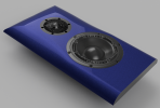
The plan is for a faceted enclosure. In this rendering (please excuse random drivers where the Purifi and DXT go - does anyone have models?), baffle width at the bottom and driver placements are identical to r1. The height is a bit shorter than the Denovo flat pack: 13.75" instead of 16. Facets are cut back 30 degrees from the face as viewed from the top, along the tangent line that clears both drivers by 3 mm.

Per the rendering, the intent is that the cabinet is solid wood (white oak, most likely), so special steps to deaden the enclosure might be necessary.
The PR goes on the back as in the r1. It'll probably be the SB Racetrack, but we shall see...
At the outset, thanks go to @Rick Sykora, @ctrl, and others for all of your work and for all that you've shared.
Primary departures from the r1 priorities are
- Loosened (discarded?) the relatively easy to build constraint. I'm not relying on a flat pack. See below for more challenging-but-doable changes in the woodworking category.
- Intent to push the volume down a bit.
- Planning for a passive crossover.
The plan is for a faceted enclosure. In this rendering (please excuse random drivers where the Purifi and DXT go - does anyone have models?), baffle width at the bottom and driver placements are identical to r1. The height is a bit shorter than the Denovo flat pack: 13.75" instead of 16. Facets are cut back 30 degrees from the face as viewed from the top, along the tangent line that clears both drivers by 3 mm.
Per the rendering, the intent is that the cabinet is solid wood (white oak, most likely), so special steps to deaden the enclosure might be necessary.
The PR goes on the back as in the r1. It'll probably be the SB Racetrack, but we shall see...
") . For Qa (stuffing) and Ql (leakage), I’ve used what
. For Qa (stuffing) and Ql (leakage), I’ve used what 
 . 3DWarehouse (Sketchup only?) has the DXT but login/download doesn't seem to work...