• WANTED: Happy members who like to discuss audio and other topics related to our interest. Desire to learn and share knowledge of science required. There are many reviews of audio hardware and expert members to help answer your questions. Click here to have your audio equipment measured for free!

Semi classic 3-way with AMT (off-axis measurements included)

XMechanik

Member
Forum Donor
Joined
Oct 27, 2022
Messages
46
Likes
125
Location
Warsaw
wy.jpg

Trying a 3-way design. The goals as always: balanced SPL and directivity related characteristics (acoustic power response, in-room response etc).

Drivers used:
tweeter : AMT2-4 link
midrange: RS100-4 link
woofer: DC160-8 link

I started from what I had of the shelf and these were RS100-4 and DC160-8. I had also a dome tweeter but I thought it was a good opportunity to play around with ribbon or AMT driver as the midrange (RS100-4) is a fullrange driver and can be filtered high.

The box is made of 18mm birch plywood with external dimensions 185x395x293mm. The volume for the woofer is approximately 12.5 liters, for the midrange there is a closed chamber with a volume of 1 liter. Bass reflex for the woofer tuned to ~40Hz. The box is filled with polyester fiber.

front_panel.png

Front panel diagram above, dimensions in mm.

Due to the asymmetrical arrangement of the drivers, the measurements were taken for angles 0-350 on both orbits (H and V). Upgrading Clio Pocket to version 3 was very helpful for this task. It has an auto saving functionality, which makes the collection of off-axis characteristics few times faster, also with using a manual rotary table.

During the measurement session with manual angle adjustments you have to walk a bit. Out of curiosity, I estimated that a distance of about 1.3 km is covered (36 measurements per orbit x 2 orbits x 3 transducers x 3 m distance from the laptop to the rotary table + return).

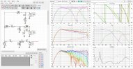
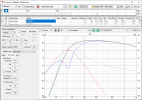
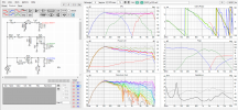
After processing and merging I entered all characteristics into XMachina software, which generated a number of solutions. I transferred one of them to VituixCad.
m323_VC6p.png
Attached VituixCad *.VXP file, FRD and ZMA measurements (for what it's worth): LINK

The circuits are not complicated and could be further simplified. It seems that applying R7-C10 branch was not nesesery, it creates a trap that removes a peak in the woofer response at 3kHz. The peak untrapped is over 20dB lower than the system spl so I think the branch could be safely omitted.

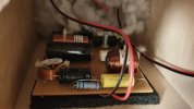
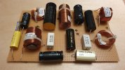
The filters are assembled on an universal PCB with copper strips along the entire board. Filters are mounted with a screw on an anti-vibration pad.
fpcb.jpg fmont.jpg

In the midrange THD level is lower than the fundamental component by more than 50dB (1m, 86dB)
thd_m323.jpg

This is great improvement comparing to my previous design (link). For that design (with SB and Scan Speak) it was only 37dB. I suspect it was caused by the midwoofer cone breakup resonance which was exited by third harmonic leakage from the midwoofer's pass band. The midrange driver in this 3-way system has small diameter comparing to the midwoofer in the 2-way (10cm vs 15cm), it's breakup frequency is higher and not so easy to reach by harmonics from the pass band. From the distortion perspective the system is limited by the woofer as it's is not a Xmax champion :)
 
Last edited:

eddantes

Addicted to Fun and Learning
Joined
May 15, 2020
Messages
717
Likes
1,421
looks very nice!
 

alex-z

Addicted to Fun and Learning
Joined
Feb 19, 2021
Messages
914
Likes
1,694
Location
Canada
Great work!

Preference score comes out to 5.7, or 7.9 with sub. Although those numbers may be artificially high, as the smoothing introduced by gating boosts them.

For anyone wondering, here is what the speaker looks like with the 50dB scaling, and polar maps that Amir normally uses. Normalized to SPL with 3dB contour lines.


SPL.png
Directivity (hor).png
Directivity (ver).png
 
OP
XMechanik

XMechanik

Member
Forum Donor
Joined
Oct 27, 2022
Messages
46
Likes
125
Location
Warsaw
Preference score comes out to 5.7, or 7.9 with sub. Although those numbers may be artificially high, as the smoothing introduced by gating boosts them.
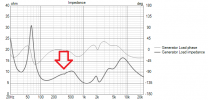
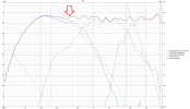
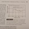
I think you're right. Here is an example from Toole's book and it may be similar here. the impedance graph shows a trace of resonance at 370 Hz. It is almost invisible on the SPL characteristics, but the measurement conditions allowed only for 5 ms gate, for the example from the book it was much better, i.e. 10 ms and the resonance was masked.

resonanceOnZ.pngresonanceOnSpl.pngFTbook.jpg
 
Last edited:

Matt_Holland

Active Member
Joined
Sep 3, 2023
Messages
259
Likes
433
I started from what I had of the shelf and these were RS100-4 and DC160-8. I had also a dome tweeter but I thought it was a good opportunity to play around with ribbon Bass reflex for the woofer tuned to ~40Hz. The box is filled with polyester fiber.
Nice! Very handsome cabinets.
From the impedance graph it looks like the reflex tuning is around 35-37Hz and from the SPL graph the bass alignment looks de-tuned. Is this the case? If so was it deliberate and did you consider a higher tuning frequency to get more SPL between 50-100Hz?
 
OP
XMechanik

XMechanik

Member
Forum Donor
Joined
Oct 27, 2022
Messages
46
Likes
125
Location
Warsaw
Nice! Very handsome cabinets.
From the impedance graph it looks like the reflex tuning is around 35-37Hz and from the SPL graph the bass alignment looks de-tuned. Is this the case? If so was it deliberate and did you consider a higher tuning frequency to get more SPL between 50-100Hz?
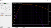
Thank you. BR tuning was aiming 40Hz (but it turned out to be maybe 1-1.5Hz less) because it resulted in the highest level at 40Hz in the enclosure simulations. Even though the simulations are not fully confirmed in reality I don't feel there is lack of 50-100Hz representation.
m323_br_tune_sim.png enclsim_vs_xosim.png
 

BenB

Active Member
Joined
Apr 18, 2020
Messages
284
Likes
446
Location
Virginia
Nice project. Thanks for sharing. Any reason the mid is more offset horizontally than the tweeter is?
 

Trouble Maker

Addicted to Fun and Learning
Joined
Jan 6, 2020
Messages
679
Likes
733
Location
Columbus, Ohio, US
I'm a novice, so I'm curious about a few things.
I'm trying to understand how the driver alignment affects the results.
Is on axis in alignment with the tweeter?
Why not align the tweeter and mid? <-Sorry, just saw the same question above.
What positives and negatives do you see in offsetting the mid and tweeter from the woofer?

Very nice results overall!
 

abdo123

Master Contributor
Forum Donor
Joined
Nov 15, 2020
Messages
7,446
Likes
7,955
Location
Brussels, Belgium
Does this sound exciting in real life?

The spinorama has a very steep roll-off. Usually i aim for 0.6 to 0.8 db/oct
 
OP
XMechanik

XMechanik

Member
Forum Donor
Joined
Oct 27, 2022
Messages
46
Likes
125
Location
Warsaw
Nice project. Thanks for sharing. Any reason the mid is more offset horizontally than the tweeter is?
I'm trying to understand how the driver alignment affects the results.
Is on axis in alignment with the tweeter?
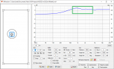
I simply tried to reduce diffraction effects by changing locations of the drivers. As a result of the horizontal offset the main lobe may have a slight side tilt near the crossover frequency, but I can't imagine whether this could have any audible effects.
Attached results from VituixCad diffraction tool with pass bands marked.
m323_difr_AMT2-4.pngm323_difr_rs100.png
 
OP
XMechanik

XMechanik

Member
Forum Donor
Joined
Oct 27, 2022
Messages
46
Likes
125
Location
Warsaw
Does this sound exciting in real life?

The spinorama has a very steep roll-off. Usually i aim for 0.6 to 0.8 db/oct
I'd rather not bright the sound any further. But maybe that's because my listening environment is quite reflective.
 
Last edited:
Top Bottom