Hi
Ok, I think I can shed more light on this.
Basically we are normally dealing with a loudspeakers magnitude response, logical, as this is the primary thing but not only things we hear.
With a real crossover, one has to deal with and include the upper and lower drivers frequency response and phase, to make it simpler, we will ONLY consider the crossover filter portion here.
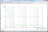
First, simulate Speaker1, a perfect single driver loudspeaker, lets say who's bw is that of a sealed box, response flat to 30Hz and has a 4th order low pass at 20Khz.
I did this here with a separate high pass and low pass block, summed together and fed into a perfect Naryabump EL Flatatron transducer.
The loudspeakers acoustic phase is shown with all the fixed delay like time of flight to the microphone removed. This is the phase response that indicates where the driver is in time relative to another frequency in time.. You see it follows the minimum phase relationship between mag and phase that nearly all single drivers mostly obey over some bandwidth.
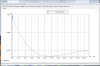
Speaker2 is a two way speaker made with two more perfect drivers with the same bandwidth and also has a 2nd order high pass and low pass L&R crossover at 500Hz.
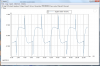
The following displays are all different views of the same events (like how the impulse response and mag and phase are tied through the FFT and IFFT process), the one not normally shown with loudspeakers is the square wave response.
This is a complex wide bandwidth signal where it is also easy to recognize corruption or alteration visually.
For a single source like in an electronic signal, one can read the square wave something like this.
An angled top and bottom reflects insufficient LF response, flat mag and phase response to DC would have a flat level top and bottom.
The vertical portions are tied to the HF bandwidth as the upper bandwidth is limited, the square eventually becomes a triangle wave when fully "slew limited".
To look "perfect" on an oscilloscope, one needs flat mag and zero acoustic phase from about 1/10 the F to 10X the square wave, frequency making it a hard signal to reproduce well or over a broad bandwidth.
So what if we have a normal 2 way loudspeaker with two perfect drivers with exactly the same frequency response, is that different?
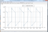
Well with all the named filters one can get flat magnitude response and what one sees is that there is a phase shift from high to low that ultimately reaches 90 degrees times the filter order. Here it is a 2 way speaker 2nd order L&R HP / LP crossovers at 500Hz.
I matched the frequency responses so one can see that in addition to the normal minimum phase relationship (where any change in frequency response has a corresponding phase response) one also has an extra 180 degree "all pass" phase shift (phase shift without a change in amplitude) that the crossover has added.
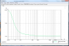
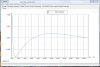
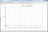
You can see that the impulse response has changed a little bit but the step response is pretty different. I hesitated to put Group Delay in, too many people look at the numbers and don't understand them and think subwoofer are bad because big numbers seem like bad juju.... Group Delay means what it sounds like, the difference in time between one group of frequencies vs another.
It displays a delay and cannot go negative (requiring the illusive predictive circuit for that).
In Group delay, one can see a different view of the all pass phase shift where the lower portion right below crossover is later in time than the upper part.
The thing one must keep in mind though is that what 1ms means depends on / scales with the frequency. In other words, any given filter slope or change in response shape at 10KHz produces 100 times more group delay at 100Hz, anything at 20Hz lasts 1000 times longer than 20,000Hz
With the Step function and especially the Square wave signal, one can see the transmogrification of the wave shape where some of the frequency components are in a different "time zone" (shifted in phase) compared to others.
When using FIR DSP to correct loudspeaker phase, what one does (I like Re-Phase) is delay everything back to the farthest behind (normally lowest frequency) part you have Taps and allowable latency to correct to. In this speaker, one could FIR to correct the phase to equal speaker 1 and so you have the same group delay, square wave responses etc.
I hope i can post all the curves, if on they will be in a second post. Ok they are in a different order, look at mag, impulse step, gd square
Best,
Tom Danley