I did a simple simulation and it seems like the phase shift between LF and HF outputs of the crossover is around 218deg, which is much closer to 180deg compared to 0(360)deg. LF driver has impdance around 6ohm at 3.2kHz, so I used a 6R resistor in my model. Impedance of the tweeter is flat across the frequency range, 4R.
Unfortunately, that's not how crossover design works.
To put it bluntly, simplified and abbreviated, what happens electrically is "irrelevant". Ultimately, only the acoustic curve of the filter slopes counts.
When considering the electrical filter, the contribution of the chassis is completely missing. Even with an electrical equivalent circuit for the chassis, the reality is only partially represented.
Therefore, it is always the acoustically measured filter slopes that count. These are shown in SPK5 and can be evaluated.
It clearly shows that the filter slopes correspond quite well to a 4th order filter.
In order for the phase alignment of the drivers to fit around the crossover frequency, one has to slightly readjust the filters, since the "sound source plane" of the tweeter and woofer are different - the "sound source plane" of the woofer is offset by about 0.03m to the "rear".
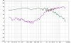
That the alignment of the phases is correct is also shown in the SPK5 app note. The blue curve shows the frequency response when a driver polarity is reversed, so the phases should cause maximum cancellation.

") ).
).