• WANTED: Happy members who like to discuss audio and other topics related to our interest. Desire to learn and share knowledge of science required. There are many reviews of audio hardware and expert members to help answer your questions. Click here to have your audio equipment measured for free!

Introducing Directiva - An ASR open source platform speaker project

D!sco

Senior Member
Joined
Jun 16, 2021
Messages
498
Likes
399
The depth of the cabinet does not play a decisive role in the Directiva r2, but still contributes to the radiation pattern.

If you really plan to build a bookshelf speaker with a significantly greater depth, the radiation pattern will change somewhat.
When the time comes you can contact me, then I can simulate for you how big the effects will be compared to the original r2.

Update: Of course only if your design is open source again ;)
Hahaha, maybe I'll sell it. You never know! The Directiva team has done some stellar work so far, a lot of it looks at least as good as many professional examples. With some work and marketing, they could compete with some serious products. I have no doubt that monitor would have similar value.

I'd love to learn what makes a cardioid enclosure tick, especially since I'm hoping to use these techniques in the future. My first goal would be to see if it works in a PVC pipe, the easiest enclosure to fabricate. Maybe a 3D printed cardioid cone enclosure after. This is a cool project to watch.
 

Martyreasoner

Member
Joined
Nov 10, 2021
Messages
44
Likes
38
A quick visualization of bass module sizes, assuming a desired 43" tweeter height (110 cm)

View attachment 180209

From left to right: 4x 15cm" drivers, 2x 17cm drivers, 1 x 23cm, 2 x 23 cm, 1 x 27cm, 1 x 12".
Interesting. What are the proposed rear driver configs for cardioid. Also are we assuming this will be ran off of a hypex plate amp?
 

thunderchicken

Active Member
Joined
Feb 5, 2019
Messages
152
Likes
150
Location
Seattle
A quick visualization of bass module sizes, assuming a desired 43" tweeter height (110 cm)

View attachment 180209

From left to right: 4x 15cm" drivers, 2x 17cm drivers, 1 x 23cm, 2 x 23 cm, 1 x 27cm, 1 x 12".
I think the 2x23cm version is ultimately what I'd go with, but I'm thinking WAF will be pretty high with the 2x17cm and 4x15cm versions.
 

TimVG

Major Contributor
Forum Donor
Joined
Sep 16, 2019
Messages
1,199
Likes
2,646
For those wondering what R2 with a bass module may look like on paper. My own midbass/mid cabinet (avatar) which is used in combination with a narrow directivity horn will serve as bass cabinet for the time being while I evaluate crossover and voicing configurations (for my own use). It laso features a somewhat controlled behaviour at lower frequencies, although it was my first attempt at such a model and it's not as good as I could make one now. I cross to my subs at 80 or so Hz.

I luckily still had the anechoic measurements from my bass cabinet, in combination with the R2 top module (a minor adjustment in baffle step is not visualised as they were not measured as such) we get the following:

1642868030936.png


1642868211335.png
 

D!sco

Senior Member
Joined
Jun 16, 2021
Messages
498
Likes
399
A perfect sub crossover point, to boot.
 

Lbstyling

Addicted to Fun and Learning
Forum Donor
Joined
Jan 2, 2019
Messages
502
Likes
464
For those wondering what R2 with a bass module may look like on paper. My own midbass/mid cabinet (avatar) which is used in combination with a narrow directivity horn will serve as bass cabinet for the time being while I evaluate crossover and voicing configurations (for my own use). It laso features a somewhat controlled behaviour at lower frequencies, although it was my first attempt at such a model and it's not as good as I could make one now. I cross to my subs at 80 or so Hz.

I luckily still had the anechoic measurements from my bass cabinet, in combination with the R2 top module (a minor adjustment in baffle step is not visualised as they were not measured as such) we get the following:

View attachment 181006

View attachment 181007
Nice!

I assume the DI peak at crossover cannot practically be improved further as its a C to C spacing issue. If this is correct, is it possible to router into the edge of the horn so the bass driver can get closer?
 

TimVG

Major Contributor
Forum Donor
Joined
Sep 16, 2019
Messages
1,199
Likes
2,646
I'd like to premise by stating this is not the final crossover, just a visualisation of what I'm currently trying.

is it possible to router into the edge of the horn so the bass driver can get closer?

Not an option, sorry. Fwiw this kind of thing is not going to be audible in the slightest, there's no hint of a dip in the direct sound or even up to (and beyond) +/-10°.

It's funny as I expected this would come up at one point. I even discussed it with the other team members some time ago: Do we design for the best looking spinorama and estimated in-room response to avoid discussion, or move against this if we feel it makes for a better practical loudspeaker.

We could design it as such that the peak is gone completely, even in the DI. You have to remember though that these are averages, once we start looking at the individual curves then you'll start to see other anomalies, such as a peak around crossover above or below the acoustical axis, meaning a timbral shift as you move up and down. The closer you are the more pronounced this could be. This particular configuration as it is now however, has quite a large vertical window as well.

1642878709448.png


This is my take on it, the team will decide together on a final crossover, and it could very well be quite different from this one, I don't know yet.
Just be aware that a perfect spinorama doesn't always mean a better practical result (although the spinorama looks pretty nice as it is).
 

fluid

Addicted to Fun and Learning
Joined
Apr 19, 2021
Messages
694
Likes
1,198
Nice!

I assume the DI peak at crossover cannot practically be improved further as its a C to C spacing issue. If this is correct, is it possible to router into the edge of the horn so the bass driver can get closer?
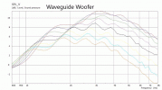
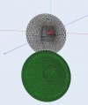
Splitting a waveguide with a woofer to narrow the CTC distance can have quite a negative effect on the performance of the waveguide. If you can't get the drivers within a 1/3 WL distance or closer often the best trade off position is then further away. Unless you are trying to create interference from the 0.5 to 0.7 wavelength spacing those distances are best avoided.

Example from here shown below
https://www.diyaudio.com/community/...aker-build-abec-modelling.357792/post-6492454
 

Attachments

  • Split.gif
    Split.gif
    273.4 KB · Views: 154
  • Waveguide Woofer Split.jpg
    Waveguide Woofer Split.jpg
    109.5 KB · Views: 158

Lbstyling

Addicted to Fun and Learning
Forum Donor
Joined
Jan 2, 2019
Messages
502
Likes
464
I'd like to premise by stating this is not the final crossover, just a visualisation of what I'm currently trying.


Not an option, sorry. Fwiw this kind of thing is not going to be audible in the slightest, there's no hint of a dip in the direct sound or even up to (and beyond) +/-10°.

It's funny as I expected this would come up at one point. I even discussed it with the other team members some time ago: Do we design for the best looking spinorama and estimated in-room response to avoid discussion, or move against this if we feel it makes for a better practical loudspeaker.

We could design it as such that the peak is gone completely, even in the DI. You have to remember though that these are averages, once we start looking at the individual curves then you'll start to see other anomalies, such as a peak around crossover above or below the acoustical axis, meaning a timbral shift as you move up and down. The closer you are the more pronounced this could be. This particular configuration as it is now however, has quite a large vertical window as well.

View attachment 181062

This is my take on it, the team will decide together on a final crossover, and it could very well be quite different from this one, I don't know yet.
Just be aware that a perfect spinorama doesn't always mean a better practical result (although the spinorama looks pretty nice as it is

Splitting a waveguide with a woofer to narrow the CTC distance can have quite a negative effect on the performance of the waveguide. If you can't get the drivers within a 1/3 WL distance or closer often the best trade off position is then further away. Unless you are trying to create interference from the 0.5 to 0.7 wavelength spacing those distances are best avoided.

Example from here shown below
https://www.diyaudio.com/community/...aker-build-abec-modelling.357792/post-6492454
Well well, Learned something today!

This is not how I understood it works, but makes total sense given some experience with room nodes.

Thank you!
 

abdo123

Master Contributor
Forum Donor
Joined
Nov 15, 2020
Messages
7,446
Likes
7,955
Location
Brussels, Belgium
Oh just once really with a quick, on the spot, experimental crossover - basically just focussed on the on-axis. Sounded pretty good!

In fact you can check it out here:

Thank you for sharing! I love these moving videos that you do with your cardiods hahaha.

Truth be told it's difficult for anything to sound band in such a space ;).
 

TimVG

Major Contributor
Forum Donor
Joined
Sep 16, 2019
Messages
1,199
Likes
2,646
Thank you for sharing! I love these moving videos that you do with your cardiods hahaha.

Truth be told it's difficult for anything to sound band in such a space ;).

Oh I guarantee you i've had plenty of bad stuff passing here :)

In all honesty it did sound quite good, and I may be underselling that a bit at the moment, but I need to check them out in my listening space first. Perhaps I should say they sound as good as the measurements indicate they should.
 

Lbstyling

Addicted to Fun and Learning
Forum Donor
Joined
Jan 2, 2019
Messages
502
Likes
464
Oh just once really with a quick, on the spot, experimental crossover - basically just focussed on the on-axis. Sounded pretty good!

In fact you can check it out here:


I can't remember the effect of the direct Vs reflected sound in any other demo video being quite so obvious a transition as when you walk back in this video.

Also notable lack of 'boomyness' as you walk round (as expected I suppose!)

I would be I tested to see the distortion figures also.

It's looking like a mighty strong design.
 
Last edited:

617

Major Contributor
Forum Donor
Joined
Mar 18, 2019
Messages
2,434
Likes
5,387
Location
Somerville, MA
@TimVG I'm not sure if we've discussed it privately but what are your impressions of output/distortion/ stress testing?
 

TimVG

Major Contributor
Forum Donor
Joined
Sep 16, 2019
Messages
1,199
Likes
2,646
I tested the top module without a high pass on some bass heavy tracks, and while there was no real output in the low range, and quite a bit of driver movement, I could not detect any audible distortion. I'm going to fire them up tomorrow in a 3-way configuration and see what happens. My horns are as dynamic as they come so it should be interesting.
 

Newman

Major Contributor
Joined
Jan 6, 2017
Messages
3,530
Likes
4,371
...For those who might be surprised by the number of versions, along with different midwoofers, gave waveguides a shot too. ...

Hi Rick,

could you perhaps edit post #1 from time to time, so that it starts with links to the posts in the thread that represent the 'most current' design details for this project?

If not, can you point me to the key posts please?

I have quite lost track.

cheers
 
Top Bottom