• WANTED: Happy members who like to discuss audio and other topics related to our interest. Desire to learn and share knowledge of science required. There are many reviews of audio hardware and expert members to help answer your questions. Click here to have your audio equipment measured for free!

Directiva r1.2 design and build

OP
A

Alan J

Member
Joined
Jul 14, 2020
Messages
64
Likes
88
Bottom facets are cut, and edges are aggressively rounded. Rounding was limited by the 3-5 mm distance from facet lines to driver openings, and I don't think it will have a major effect on the measured responses. I do expect effects - the baffle step peak moving a bit up in frequency and being somewhat blunted - from the additional faceting. But we shall see.

I glued the baffle, giving up on making it changeable without replacing the sides, as this made it far easier to cut the facets. This now feels like a classic compact bookshelf speaker. Personally, I like the stripey look, especially with the softened edges.

I took about an inch off of the depth to bring the interior volume down to about 10.25 liters after compensation for the drivers. (With the double thickness baffle, my estimate of volume lost to the drivers and PR was only 0.25 liters). 37 grams on the PR brings the calculated fb to 37 Hz.

IMG_4091.jpeg


At first opportunity, I'll be repeating impedance, near field, and far field measurements.
 
OP
A

Alan J

Member
Joined
Jul 14, 2020
Messages
64
Likes
88
Measurements are complete, and checked (and corrected for) any change in microphone distance after repositioning on the stand for horizontal and vertical measurement sets or for alignment with the driver axes.

2D baffle simulation suggested that the baffle step would move up a bit in frequency and the hump softened a bit. In these measurements, any such effect is pretty subtle. Matching magnitudes at 200 Hz, the response with full facets is down about 1 dB at around 1.2 KHz and up about a dB around 2.2. I'm showing an r1 response in the graph as well, which is of course from a different driver.

1703080271280.png


It seems useful to compare directivities of the raw driver responses. Here they are, for r1, upper facets only, and full facets with aggressive softening of the edges. Looking at the DXT, it does appear to benefit from the upper facets, with no additional effect from lower facets or softening of the edges. This is entirely unsurprising. Looking at the Purifi in and around the crossover region (1-4 KHz), adding the upper facets seems to be helpful but we lose some of that improvement when adding the lower facets.

1703079237311.png


Here's the power and DI panel from a candidate crossover (similar to what was posted before). I'm not done with it, but it's looking OK, and I suspect that the faceting will be staying for aesthetic reasons.

1703081431465.png
 

Attachments

  • 1703079982794.png
    1703079982794.png
    34.3 KB · Views: 23
  • 1703079910428.png
    1703079910428.png
    43.8 KB · Views: 24
  • 1703079817802.png
    1703079817802.png
    47.2 KB · Views: 24
  • 1703079768504.png
    1703079768504.png
    47.2 KB · Views: 28
OP
A

Alan J

Member
Joined
Jul 14, 2020
Messages
64
Likes
88
I'm prepping for a listening test in the "customers'" apartment. Here's a 3.5ms window response compared with the VCAD prediction (so ignore below 300 Hz). This is with 1/6 octave smoothing. The crossover is a DSP-implemented LR4 @2200 Hz. The Purifi LP is 2nd order Butterworth and the Purifi HP is 3rd order, in order to get approximate phase matching at the crossover point.
1703956650634.png


Correspondence is great, especially above 1 KHz where the measurements have decent resolution. REW's EQ function needs to be set for a 1 dB flatness target in order to come up with anything, though to me we're a teeny bit hot between 1 and 10 KHz.

Though I'm not evaluating this plywood box, other than to verify that similar materials are unlikely to need added structure, distortion seems to be dominated by the known Purifi basket mode, which shows up as multiple harmonics and lines up exactly with a tiny ripple in the impedance curve. Some of the baffle ideas we're tossing around would call for driver mounting methods conducive to isolation. For example, if we go with solid wood, oversized mounting holes with grommets or front/rear mounting rings may be called for. There are some postings over at DIYAudio suggesting that such mounting can tame the purported basket mode. It's 25 dB down and high Q, so whether it matters is a relevant question.
Distortion R2.png
 

Attachments

  • 1703956404760.png
    1703956404760.png
    45.6 KB · Views: 25

Paweł L

Member
Joined
Aug 18, 2021
Messages
99
Likes
46
Here is my admittedly inexperienced attempt at a passive crossover based on your last project post. Would need more optimizing once you get to measurements on the real speaker. Notably, since your target location is a bookshelf, expect more bass and some adjustments there. Only 7 elements...

View attachment 332062
So I played a bit with your Vituix passive x-o files, the ones before this post and changed things a little since the impedance above midrange dropped too much in my opinion because of the RLC filters in the tweeter section. Also changed the location and values of the resistors to keep the amp more or less happy. How it would sound, I have no idea, overall things look pretty flat for simple LR4 x-o, but I bet it would require some measurements and tuning by ear.
 

Attachments

  • Directiva1.2Revised x-o.zip
    3.1 MB · Views: 60
OP
A

Alan J

Member
Joined
Jul 14, 2020
Messages
64
Likes
88
So I played a bit with your Vituix passive x-o files, the ones before this post and changed things a little since the impedance above midrange dropped too much in my opinion because of the RLC filters in the tweeter section. Also changed the location and values of the resistors to keep the amp more or less happy. How it would sound, I have no idea, overall things look pretty flat for simple LR4 x-o, but I bet it would require some measurements and tuning by ear.
Thanks! I will take a look. My attention definitely could have drifted away from the impedance chart. I've done a lot of optimizing in VCAD with the minimum set to 3.2 but maybe a bit higher is better and the optimization routine imposes a penalty for going below, not an absolute guarantee.

Meanwhile, we are visiting at the intended listening locale. We are using a DSP-based LR4 @2200 Hz, close to phase-matched at the crossover point with no delays (my "don't do anything I couldn't do with passives" DSP crossover). The prototype sounds wonderful in-room. Folks are astounded by how the single speaker paints the room and reaches into adjacent spaces with un-colored sound. Sitting in the intended location on a 26" high console that runs across the front of the room, bass is present and clean-sounding - never boomy - down to at least the high 30's. I'd planned on playing with PR tuning but I don't know if we'll touch it.

We're making final (?) aesthetic decisions this weekend. It looks like full facets will stay, and the DXT-Purifi spacing will stay the same while lowering the drivers about an inch.
 
OP
A

Alan J

Member
Joined
Jul 14, 2020
Messages
64
Likes
88
Aesthetic decisions made last weekend:
  • Keep the woofer-tweeter spacing as well as the baffle dimensions, but lower both drivers about an inch on the face.
  • Keep what we're calling full faceting: sides (tangent to the drivers) and center on both top and bottom
  • Absent any new revelations, baffle to be solid wood
  • Balance of enclosure likely to have a contrasting, possibly painted finish
The rendering below uses "3D Cherry" and black powder coat from Fusion 360. Natural cherry will be lighter in tone than what's shown here.

But baffle species is TBD. Factors in selection are
  • Availability!
  • Stability of properly dried stock (could mean quartersawn stock or a low ratio of tangential to radial dimension change with humidity/water content)
  • Dimensional change in use (could mean quartersawn stock or a species with relatively low tangiential dimension change)
The baffle will need either to be gasketed and held in place in a manner that allows some movement, or glued with compliant adhesive to an MDF or plywood panel that's conventionally glued to the sides of the enclosure. The former is more complicated, but not terribly so, and doesn't waste any volume. It might also help with Purifi basket resonance.

I'll also need to allow for some movement in the driver mounting. The worst-case movement of a mounting screw hole should be under 1 mm, but it still will mean care in how the drivers are held in place. Options include oversized mounting holes with grommets/gasketing or a mounting ring set into the baffle.

Off to the local wood stock supplier (who makes guitars and knows about stability!). I may go silent for a bit while sorting through options.
 

Attachments

  • Directiva_minimal_faceted_2024-Jan-08_01-13-56AM-000_CustomizedView16282559864.png
    Directiva_minimal_faceted_2024-Jan-08_01-13-56AM-000_CustomizedView16282559864.png
    316.1 KB · Views: 157
Last edited:
OP
A

Alan J

Member
Joined
Jul 14, 2020
Messages
64
Likes
88
Someone asked by DM for a drawing of the baffle, so here it is as .pdf and also as .dxf. Dimensions are in mm.

All of the facet cut lines on the baffle face are 8 mm from their respective driver opening tangent lines. In the prototype, this dimension was more like 4 mm but we decided to allow for more aggressive rounding. [EDIT] The corner and horizontal bottom facets as drawn here are 25 degrees while the horizontal top facet is at 55 degrees. The steeper angle at the top makes (IMO) the intersection of the three upper facets simpler and cleaner looking. These angles have no effect on the dimensions on the face; they affect only the placement of the cut lines along the sides. Of course, the angles affect the minimum thickness of the baffle. Put another way, for a given baffle thickness, the angles determine whether the facets cut into the side wall panels and how much baffle thickness is available to contribute to mounting and stability.

Some explanation may be needed regarding the notes regarding facet cut lines. Without the aid of photos or drawings that I don't have in hand, this may be easier to do than to describe! For the upper-right angled facet, the cut line on the baffle surface is on the drawing. The cut line along the side of the baffle goes from the same point along the righthand edge of the baffle, 256 mm down from the top, to a point along the upper-right edge, 29 mm back from the face. Similarly, for the bottom-right facet, one cut line is on the face as drawn, while the other extends from the right hand edge, 129 mm up from the bottom, to a point along the bottom-right edge 32 mm back from the face.

For each corner facet, those two lines define the triangular piece to be removed. I cut them by placing pieces of metal bar stock parallel to the cut lines, adjusting the distance between the edge of each bar and the cut line so that a saw leaning against the two bars would almost hit the cut line. It's easier than it sounds. The metal bars guard against cutting too deep.

The horizontal top and bottom facets are simpler to lay out: For each, one cut line is a horizontal line on the face, as drawn. The other is on the top or bottom face of the panel, the indicated distance from the front.

I found it easiest to lay out and cut the corners, then the top and bottom.
 

Attachments

  • Baffle.pdf
    26.8 KB · Views: 57
  • Baffle.dxf.zip
    8.8 KB · Views: 34
Last edited:
OP
A

Alan J

Member
Joined
Jul 14, 2020
Messages
64
Likes
88
Yes - all limited to the aesthetics and woodworking front...
  1. Took a lot of time to decide on the baffle material: black cherry. The balance of the enclosure will probably be birch or cherry plywood stained black but that's not finalized.
  2. Located and purchased stock, cut baffle blanks
  3. Bought a 3D printer, set up, and designed and printed jigs for cutting openings, insets, and facets. For the openings, the jigs don't do anything that you can't do with a common circle jig (other than rough out the cutouts for the tweeter leads), but they do save a lot of time. For the facets, they're a life-changer.
  4. Cut openings/insets and began cutting facets. It goes quickly, so these ought to be finished this weekend.
Action shots below. Once the facets are cut, I'll move on to enclosure construction including more thinking about baffle attachment to allow some movement. Cherry is a stable species but we'd expect a millimeter or two change in width at humidity extremes in reasonably climate controlled environments. I'm also thinking about details of driver mounting (insets are cut in anticipation of slightly thicker than usual gaskets), with an eye toward being sure that 400 Hz area resonance doesn't show up as distortion at the level that it did in the plywood prototype.

So I may continue to be pretty quiet unless anyone's interested in more construction action shots.

Directiva_minimal_faceted_2024-Jan-20_03-53-25PM-000_CustomizedView44903430186.pngIMG_4254.jpegIMG_4255.jpegIMG_4259.jpegIMG_4260.jpegIMG_4263.jpegIMG_4270.jpeg
 

Paweł L

Member
Joined
Aug 18, 2021
Messages
99
Likes
46
The baffle as in the last picture looks nicer than in the first, at least to me. It supposedly also behave better regarding the acoustics. And easiest to make. I assume the opening for woofer driver will be routed at 45 deg to avoid unwanted back wave reflections - make the Purify breath as freely as possible.
 
OP
A

Alan J

Member
Joined
Jul 14, 2020
Messages
64
Likes
88
The lower facets were an aesthetic choice made in concert with the people who will own these, supported by listening tests with the prototype.

I'vm planning on chamfering the inside to make space for air flow, but not until finalizing mounting.
 

D!sco

Senior Member
Joined
Jun 16, 2021
Messages
498
Likes
399
I’m here for vicarious project action shots. My house is full :(
 

Okankav

New Member
Joined
Apr 20, 2022
Messages
3
Likes
0
it seems front baffle has only upper facet. Is final baffle has full facet?
 
OP
A

Alan J

Member
Joined
Jul 14, 2020
Messages
64
Likes
88
All facets cut, on both baffles.

This went very quickly with the 3D printed jigs. If you look at the pics above, you can see that for each facet I printed two pieces: the main piece that fits over the baffle blank leaving the portion to be cut off exposed (5th pic above), and the second, a "cap" that forms a slot for the saw (6th pic above). If doing it again, I might skip the cap piece. Using a Japanese pull saw, I was able to lean the blade agains the main piece and get a very nice cut flush with the surface of the jig.

Now on to the enclosures. I'm presently struggling with the material decisions: plywood? MDF + veneer? any sort of CLD-type layering? The two scrap pieces in the picture are baltic birch plywood and a piece of the cherry, both stained with General Finishes black. The grain that shows through and the tone of the black look nicer on the cherry sample, so cherry plywood is a possibility, but so is a plywood or veneer whose grain and color come close.

I've noted that Alexander Heissmann uses butyl-aluminum layered with hardboard, along with steel rods, in his DXT-182 whose side panels are just a bit larger.
 

Attachments

  • IMG_4298.png
    IMG_4298.png
    733.7 KB · Views: 87
Last edited:
OP
A

Alan J

Member
Joined
Jul 14, 2020
Messages
64
Likes
88
As I make some decisions about enclosure construction, I thought I'd share a few measurements that I took to guide me. Thanks to @tktran for learnings he's shared, as well as to @augerpro for things he's shared on his website.

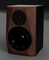
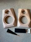
The prototype box is generic big box store 7-ply 3/4" nominal (18 mm actual) plywood, doubled for the baffle. The Purifi has the stock gasket that comes with it and is secured directly with screws into the wood. The DXT and PR are also secured by screws directly into the wood, the DXT with thin closed cell foam gasket tape (from PE), and the PR with its stock gasket. Outside dimensions of the enclosure (without the baffle) are 8.4 x 13.6" sides and 8.5 x 8.4" top and bottom. There is no cross bracing. The top and side walls are covered by a single piece of 1" thick denim insulation that wraps fully around the interior.

Questions on my mind are
  1. Do I need cross bracing? Put a better way, would cross bracing make an audible difference? A material audible difference?
  2. Is there good reason to isolate the driver, i.e., to decouple the driver frame from the baffle?
  3. Is there good reason to support the driver magnet?
Driver mounting

Taking #2 first... In this post, Lars Risbo from Purifi briefly reports on experiments done at the company. In brief, "The conclusion: just tighten the screws well and worry only about all the so many other important aspects of speaker box design." He notes that tightening the mounting screws well is important to prevent buzzing, i.e., movements between solid parts. He notes as well that supporting the magnet with a dissipative material between it and the supporting structure is helpful.

In post #64 above, I show a distortion plot where, at 447 Hz, THD is only 24 dB down from the main response. I can report that tightening the mounting screws and placing a foam pad between the speaker and the hard plastic table I was using made that peak vanish. Together with what I'll share below, this supports Lars' statement about the sufficiency of solid mounting.

That's not to say that going beyond conventional "solid" mounting won't be useful. One simple approach involves a relatively thick gasket between frame and baffle, together with a compliant washer (or O-ring) between the screw head and the frame. The "hard" mount is likely to be susceptible to loosening as the gasket material conforms over time, with thermal cycles, etc. A softer mount, whether or not the isolation makes an audible difference in this case, may be more tolerant of those changes. This is, of course, speculation.

Enclosure bracing and/or damping

The closer we are to what can be expected of the drivers, or at least to what is audible, the less need to investigate means of mitigation.

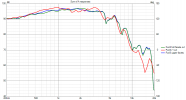
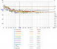
Below is the result of an un-gated in-room sweep at 1 m, for the entire signal chain, from source (TASCAM US-1x2 HR over USB) through development crossover (generic AD17xxxx 24-bit dsp), through the amp (Extron XPA-1002 PLUS), to the mounted drivers.
Purifi 1m 95 dB SPL.png

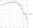
Here's the same data displayed as relative dB. if our goal is for THD to be at least 40 dB down (< 1%), we're already there down to 200 Hz, and down to about 60 Hz the peaks in THD relative to signal occur substantially due to dips in the signal.
Purif 1m 95 dB dBr.png

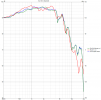
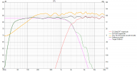
It's helpful to look at near field response. The plot below was taken at 15 mm from the Purifi cone.
Purifi nearfield SPL.png

As relative dB,
Purifi nearfield dBr.png

As helpful as I find it to look at dBr plots (saves having to mentally subtract), it's important to remember that the peak in the mid-30's correponds to the dip in the Purifi response that gets filled in by the PR in the full system response.

In Erin's testing of the driver (yes - it's the W version), his nearfield (0.3 m) showed THD to be down about 50-55 dB, down to about 120 Hz, then rising to around -25 dBr at 20 Hz. If I've read Erin's description correctly, his dBr scale is a bit different from what REW provides: he normalizes by average response over the full band, such that the dBr trace isn't affected by local variations in the main response. Still, It looks like we are (1) well below 40 dB down to the frequencies at which the driver's distortion begins to climb (see the Purifi datasheet as well), and (2) not far - perhaps as close as we could expect in a full, nothing-special signal chain - from what we should resonably expect.

[EDIT] None of this is to suggest that the enclosure, especially the sides, doesn't produce any sound. Qualitatively, probing with automotive (contact) stethoscope reveals transmission of tones particularly at the centers of the side panels. But it's tiny compared with the deafening sound (through the stethoscope) that transmits through the PR. This matters mainly to the degree to which these movements produce nonlinearities, either in the sound they radiate or in interactions with the drivers. Such nonlinearities should show up in the distortion measurements. I'm anticipating revisiting this after construction of the final enclosures, since retrofit - whether in the form of butyl pads or a combination of butyl pads and a single cross brace - would be straightforward.

In summary - At this point, I'm seeing nothing that calls for more bracing or special driver mounting. I'm still tempted to isolate the screws as described above, and still nervous about getting this right!

Comments welcomed!
 

Attachments

  • Distortion dBr at SPL 95 dB.png
    Distortion dBr at SPL 95 dB.png
    83 KB · Views: 19
Last edited:
OP
A

Alan J

Member
Joined
Jul 14, 2020
Messages
64
Likes
88
Sort of a non-update... I had a workshop injury late last week from a workpiece on the router table kicking back and hitting my hand. I was setting up a lock miter bit using scrap Baltic birch. 13,000 rpm at 0.75" radius = kickback at 58 mph. Lessons: (1) Use sleds, rollers, featherboards, etc to guide workpieces. Above all, never hand-hold undersized pieces. (2) Take multiple passes for deep cuts. Anyway, there will be a pause as I finish healing and make new fixtures.
 
OP
A

Alan J

Member
Joined
Jul 14, 2020
Messages
64
Likes
88
Someone asked by DM for facet cutting templates, so here they are as .stl files. These are all from a Fusion model of the speaker that would take me some time to clean up.

Some notes:
  • These were made for the 1.5 inch thick stock that I used for my baffles. This is relevant where the jigs wrap around the back.
  • These are mostly held in place with double-backed tape. The top and bottom jigs are amenable to being held by a single clamp.
  • The lengths of upper right and upper left jigs were limited by the Z axis of my printer but it's plenty to guide the saw.
  • For each facet, the main jig leaves the wood to be removed exposed, so it can be a guide for both cutting and sanding.
  • Adding the cap provides a 2 mm slot for the saw.
  • I used a Japanese pull saw to make my cuts. By the end of the process, I realized how easily the saw could be leaned against the jig. Even 3D printed PLA is pretty tough and tends to guide the saw well without risk of cutting into it. So the caps might not be necessary
  • Important: As you approach the end of a cut, use tape to support the weight of the cutoff piece. Otherwise there is risk of splitting along a grain line.
  • These are for my baffle dimensions and driver placement:
    • Baffle 8.5 x 13.685 in
    • Tweeter 3 in down from the top
    • Woofer-tweeter centers 145 mm apart
 

Attachments

  • Facet jigs.zip
    11.9 KB · Views: 14
Last edited:
Top Bottom