Ok, I understand.A filter changes frequency response which in turn changes measurement bandwidth/noise and harmonics. So while I could easily produce such a number, you would have no reference to compare it to.

-
WANTED: Happy members who like to discuss audio and other topics related to our interest. Desire to learn and share knowledge of science required. There are many reviews of audio hardware and expert members to help answer your questions. Click here to have your audio equipment measured for free!
You are using an out of date browser. It may not display this or other websites correctly.
You should upgrade or use an alternative browser.
You should upgrade or use an alternative browser.
Harrison Labs In-line Crossover Review (RCA)
- Thread starter amirm
- Start date
I've used them for that purpose, and later moved to the version with configurable high-pass and low-pass to feed my subs and high-pass my towers simultaneously. Both worked to my satisfaction. I used these passives up until I recently got the Mini-DSP flex. Listening to music, the digital filters in the flex don't really sound any different to me unless I listen to just the subwoofers alone. In that case I can hear more non-sub-bass content leaking through.Perfect timing. Was going to pick up a pair to use with my sub which only has lfe input and my amp which does not have sub out to see if it worked
Thanks Amir
I ordered mine directly from Harrison Labs. That web site does include the marketing-speak "Active Crossover Simulator". Good product though. It does what is needed, and in a form factor I couldn't find elsewhere.
They have what I needed:[IMG alt="Text Box: LP1 FOR WOOFER AND SUB-WOOFER AMPLIFIERS #900091
42, 44, 46, 48, 50, 52, 55, 58, 65, 70, 80, 85, 100, 120, 150, 200 HZ LOW PASS
NEW! HP-SUB ADJUSTABLE SUB-SONIC FILTER
20, 25, 30, & 35HZ HIGH PASS FILTER (Blocks Rumble)
HP1 FOR MIDRANGE AND TWEETER AMPLIFIERS #900101
50, 70, 100, 150HZ HIGH PASS CROSS-OVER
2W1 FOR 2 WAY SYSTEMS #900121
50, 70, 100, 150HZ HIGH PASS AND 42, 44, 46, 48, 50, 52, 55, 58, 65, 70, 80, 85, 100, 120, 150, 200 HZ LOW PASS
HIGH AND LOW PASS CAN BE SET TO DIFFERENT FREQUENCIES
"]https://www.hlabs.com/products/crossovers/index_files/image800.png[/IMG]
It is stereo, I bought it & it works well.
I don't care about their (or anyone else's) personal beliefs, if they will sell the product I want at a reasonable price,
then I will buy it. I do not HAVE to read about their beliefs . I'm happy with my purchase.
In my opinion it might be enough with a 12 dB/oct low pass filter if you use two subwoofers very close to each ( inverted) main loudspeaker, in stereo . No need to always try to get 24 or 36 dB/oct crossovers lowpass filtering. It depends on many things.
One example: The REL subs always uses 12 dB/oct (inverted phase) LP and thats one of the reasons they integrate well with unfiltered closed box main loudspeakers, because they drop off naturally with 12 dB/oct below box resonance.
Using only one subwoofer, ( which is bad for sound ) theres often a need for a steep filter, 36 dB/oct LP, or even more.
And then you also need a steep high pass crossover.
Last edited:
- Joined
- Oct 11, 2019
- Messages
- 1,860
- Likes
- 2,793
Nah, they aren’t knock offs. They are just old. That’s why the packaging looks different and the units themselves have corrosion.While I appreciate the time spent on this review and the member sending them to you.
These are not genuine Harrison products. These are knock-offs. Nothing about the product or packaging appears to be genuine.
I can't count the number of these I have bought and installed for numerous people over the past 10-20 years. I would bet money these are knock-offs.
They’ve had quite the reputation for many years.I use some of these in the absence of a digital crossover. Having only ever used digital crossovers, the slope options struck me as unusual but maybe that's normal for passive crossovers? they have a "tutorial" on their site about how to combine their attenuators & corssovers to compensate but these are a little pricey for what they do, so you rapidly approach the cost of a cheap digital crossover if you need to buy 2+ and an attenuator for a more "modern" slope.
As an aside, I emailed their support for 1-2 clarifications and they were friendly enough but signed the email with a few youtube URLs and description: [BTW, here's a few links revealing COVID as a hoax and how *you can fight back!*] I forget exact wording, but that was definitely the gist. I thought that was a bit forward, but hey it's their operation. Power to the people, freedom of speech, etc etc (I guess?) - similar material still on their site, it seems.
Vandersteen Audio uses the same passive filter approach for their home powered sub-woofer systems. It's a rather novel approach in this category, and uses a passive line-level filter matched to the input impedance of the amplifier powering your main speakers. I suspect the SINAD is out of this world!
solderdude
Grand Contributor
SINAD is measured at 1kHz which is -38dB at 1kHz already.
When Amir would measure the SINAD at 2V input the reference (0dB) would be 25mV.
Knowing that the AP does not report SINAD (at 2V input) above -135 the displayed SINAD would be noise dominated and show a number of around 100 as the S/N ratio of the AP is limited and the 1kHz is closer to that.
To get to see numbers above 135 one would need to feed the filter with 80V which would certainly create distortion products as (very likely) ceramic ML capacitors are used. As the filter starts shelving above 2kHz there would be some spikes messing up the SINAD. In that case not caused by noise but distortion products from the 2 capacitors. When they would be using film caps it would be lower but given the the size of the filters and the values needed for a high pass would need rather large capacitors. Ceramic ML can be small (up to 50V)
Last edited:
Are there versions of this that filter a speaker-level signal, with decent performance? I’d like to run the full speaker output to a sub, then from sub to mains with a high-pass filter like this. Would that work?
Are there versions of this that filter a speaker-level signal, with decent performance? I’d like to run the full speaker output to a sub, then from sub to mains with a high-pass filter like this. Would that work?
External high-level passive analogue filters don't work consistently because the response would be affected too much by the impedance curve of the speaker. You can find one or two on the market, but you have to buy for a specific speaker impedance, and confirm that your speaker actually has that impedance quite flat across the filter transition frequency.
The high-level filters inside speakers are obviously carefully tuned for their particular drivers.
Products like this work consistently at line level because of the high impedance of the receiving circuit.
Thank you…learned something today.External high-level passive analogue filters don't work consistently because the response would be affected too much by the impedance curve of the speaker. You can find one or two on the market, but you have to buy for a specific speaker impedance, and confirm that your speaker actually has that impedance quite flat across the filter transition frequency.
The high-level filters inside speakers are obviously carefully tuned for their particular drivers.
Products like this work consistently at line level because of the high impedance of the receiving circuit.
differenceclouds
Member
- Joined
- May 4, 2020
- Messages
- 47
- Likes
- 27
I have a pair of inline attenuators that I got from them, perfect for my application. I had an old preamp with a fixed level of noise on the output (volume independent), putting the attenuators between the pre and the power amp solved the problem perfectly. Would be curious to see how transparently they measure.
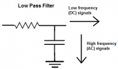
Forgive my ignorance, but can someone please clarify the purpose of the resistor in this series? I understand that the capacitor placed in parallel offers high resistance to low frequency signals and will let them pass, while shunting the high frequencies through the cap to ground, but what role does the resistor in series serve? Thanks!
Low Pass filter = 1/(2*pi*R*C) = f3dB point or half power point. When you stick a resistor inline you increase the output resistance of the source device so you'd like this value to be low so you don't have adverse effects due to possible loading of the receiving device. So based on the form factor I'd say the caps will be of questionable quality for ultra low THD levels. With different RC combinations you can change the filter response but you are restricted with the R value you can use.
Also for 12dB roll off you require 2 passive stages (RC + RC) which have Q values of 0.5 meaning you will get a slower roll off at the knee thus starting to roll off at a higher frequency than say a 2nd order butterworth that has Q of 0.7. That said perfectionists probably wont' use these devices but since you are in the low frequency of room modes maybe it doesn't matter that much.
Also for 12dB roll off you require 2 passive stages (RC + RC) which have Q values of 0.5 meaning you will get a slower roll off at the knee thus starting to roll off at a higher frequency than say a 2nd order butterworth that has Q of 0.7. That said perfectionists probably wont' use these devices but since you are in the low frequency of room modes maybe it doesn't matter that much.
That was a bit upper level for my fund of knowledge, but I appreciate it!Low Pass filter = 1/(2*pi*R*C) = f3dB point or half power point. When you stick a resistor inline you increase the output resistance of the source device so you'd like this value to be low so you don't have adverse effects due to possible loading of the receiving device. So based on the form factor I'd say the caps will be of questionable quality for ultra low THD levels. With different RC combinations you can change the filter response but you are restricted with the R value you can use.
Also for 12dB roll off you require 2 passive stages (RC + RC) which have Q values of 0.5 meaning you will get a slower roll off at the knee thus starting to roll off at a higher frequency than say a 2nd order butterworth that has Q of 0.7. That said perfectionists probably wont' use these devices but since you are in the low frequency of room modes maybe it doesn't matter that much.
In non-EE terms, could you educate me on why the resistor is there? I understand the parallel cap concept, in that I assume it offers high resistance to low frequencies, so the high AC frequencies are shunted through it to ground while the low DC frequencies are passed on through the circuit. Do I have that part correct? If so, why do you need the resistor in series?
Attachments
Last edited:
Ignoring all resistance (even self resistance of cap), a cap is essentially a charge storage device. If there is no resistor/resistance ie limiting current, a cap could charge and discharge at a very very very high rate. So in our example a very very very high rate = high frequency. So yes, energy sent to ground is attenuated. A resistor is used to slow down the charging and discharging of the cap. This will have an effect of lowering the bandwidth of the circuit. As you can see from the low pass formula if you lower resistance, the f3dB point will go up.That was a bit upper level for my fund of knowledge, but I appreciate it!
In non-EE terms, could you educate me on why the resistor is there? I understand the parallel cap concept, in that I assume it offers high resistance to low frequencies, so the high AC frequencies are shunted through it to ground while the low DC frequencies are passed on through the circuit. Do I have that part correct? If so, why do you need the resistor in series?
In order to get into it further the cap is the lower part or load of a typical voltage divider network. Words do not really describe the situation clearly. I'm sure the interpretation of the above text leaves much to be desired, sorry!!!
No, the fog is clearing and I think I’m finally using my head properly—you need both the resistor and capacitor to perform the calculations necessary to determine what frequencies to roll off. I was idiotically forgetting the entire concept of the complete circuit, where the ground comes into play, and the fact that there’s a range of LPFs that vary in terms of where to cut off the high frequencies—the resistor and capacitor values determine the cutoff frequency (fc) via the formula 1/2piRC, correct? The two components must be positioned correctly in series and parallel and then balanced to achieve the desired effect.Ignoring all resistance (even self resistance of cap), a cap is essentially a charge storage device. If there is no resistor/resistance ie limiting current, a cap could charge and discharge at a very very very high rate. So in our example a very very very high rate = high frequency. So yes, energy sent to ground is attenuated. A resistor is used to slow down the charging and discharging of the cap. This will have an effect of lowering the bandwidth of the circuit. As you can see from the low pass formula if you lower resistance, the f3dB point will go up.
In order to get into it further the cap is the lower part or load of a typical voltage divider network. Words do not really describe the situation clearly. I'm sure the interpretation of the above text leaves much to be desired, sorry!!!
In physics and engineering, the time constant, usually denoted by the Greek letter τ (tau).No, the fog is clearing and I think I’m finally using my head properly—you need both the resistor and capacitor to perform the calculations necessary to determine what frequencies to roll off. I was idiotically forgetting the entire concept of the complete circuit, where the ground comes into play, and the fact that there’s a range of LPFs that vary in terms of where to cut off the high frequencies—the resistor and capacitor values determine the cutoff frequency (fc) via the formula 1/2piRC, correct? The two components must be positioned correctly in series and parallel and then balanced to achieve the desired effect.
As the graphs indicate there are 5 tau in a near 100% charge of the capacitor.
The resister resistance in Ohms multiplied by the capacitor capacitance in Farad = 1 tau.
By varying this charge/discharge rate work can be done and changed to suit the needs at hand.


Mmmkay, the clouds are reforming. So is it fair to say in simpler terms that the resistor value essentially acts as a valve that controls the charge/discharge rate of the capacitor, and that without it the cap would essentially be at full charge consistently and would no longer serve to shunt off the high frequencies? Be kind please, was not taught this in med school…In physics and engineering, the time constant, usually denoted by the Greek letter τ (tau).
As the graphs indicate there are 5 tau in a near 100% charge of the capacitor.
The resister resistance in Ohms multiplied by the capacitor capacitance in Farad = 1 tau.
By varying this charge/discharge rate work can be done and changed to suit the needs at hand.
Similar threads
- Poll
- Replies
- 88
- Views
- 19K
- Poll
- Replies
- 52
- Views
- 11K
- Poll
- Replies
- 276
- Views
- 30K
- Poll
- Replies
- 69
- Views
- 23K
- Poll
- Replies
- 167
- Views
- 23K