• WANTED: Happy members who like to discuss audio and other topics related to our interest. Desire to learn and share knowledge of science required. There are many reviews of audio hardware and expert members to help answer your questions. Click here to have your audio equipment measured for free!

E1DA Cosmos ADC

I thought the infamous IMD hump was only exhibited by ESS DAC chips. Assuming your RME is an older unit like mine, it uses the AK4493 chip.

As you can see from the loopback results of ADI2 Pro by itself (it is the AK chip), there is no IMD hump. It only shows up when feeding ADI2 output to Cosmos ADC, not sure why.
 
See the other measurement - the ESS ADC does have the same DNA than all other ESS - IMD hump in varying degrees. It's even in the L7 measurement, you just have to look closely (hold a ruler over the graphs).

As always the hump is often covered by noise, especially with the latest generation of DACs (and ADC), where it is very small. On the Cosmos using stereo mode already covers it quite good. But noise in mono mode is extremely low, so you can see it again.

I just measured it with my APx555B as analog generator and could easily see it. That needs some more examination, the amount of hump might be dependent on input resistance, capacitive load at the input, sample rate, register settings...even chip to chip variation could be, seeing the enormous SNR differences Ivan found with the chips...

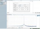
That makes sense, Matthias. I usually measure in mono/summed mode to lower noise, and that appears to have uncovered the hump.
 
Does this ESS hump only manifest in IMD measurement or is this something that could also be observed for a single tone, i.e. harmonics not monotonously shrinking as the level of the fundamental is reduced?
 
Does this ESS hump only manifest in IMD measurement or is this something that could also be observed for a single tone, i.e. harmonics not monotonously shrinking as the level of the fundamental is reduced?
It's a tiny increase in IMD when using low-level test tones (from -40dBFS to around -20dBFS). I can't imagine this is at all audible. Here's a single tone THD+N sweep vs. level, showing no hump:

1640731852607.png
 
Interesting. The IMD hump is about 10 dB and nothing to be seen in HD. I am not worried about audibility, I am interested in the mechanism. There must be some sort of nonlinearity that causes the IMD. Maybe some reference voltage that is capacitor buffered, so the LF signal starts to modulate the reference for the HF signal? If true, it should be visible with an LF single tone, too.
 
Hi Ivan,
looking at the components of the E1DA COSMOS ADC. Would it be technically possible in the future to upgrade the unit via firmware to accept up to 786khz sampling rates? To me it looks like the USB Bridge as well as the ADC would support up to 786khz. Or do I oversee some show stoppers here?
The Cosmos ADC uses a Comtrue CT7601CR USB Bridge, which is limited to PCM32/384.
However, it is not the limiting factor of the ADC's frequency response, so upgrading to a 768k-capable one wouldn't be of much use.
 
The Cosmos ADC uses a Comtrue CT7601CR USB Bridge, which is limited to PCM32/384.
However, it is not the limiting factor of the ADC's frequency response, so upgrading to a 768k-capable one wouldn't be of much use.
Ahh, I recognized, CT7601CR is up to 384khz. Only the CT7601PH is up to 786khz.
 
I received my load board and XLR wires, according to measurements in unbalanced mode, I again have very bad channel interpenetration. I installed everything from the photo. With a load of 32 ohms, the measurements turned out to be noticeably worse. Any help.
20211231_234733.jpg

unbal30load.jpg

motum4.jpg
 
Last edited:
Have you used exactly the same settings on the load board with M4 and Cosmos? What were those settings?

Have you tried using XLR directly connected to an external DAC, like M4? Just try TRS-to-XLR cables and measure M4 with Cosmos and later with M4, then compare results.
 
1. On the LOAD board, switched the last 2 switches for unbalance
2. From the photo I connected it with XLR cables from e1da.
3. Cosmos connected to laptop in 2 channel mode.
4. 3.5 jack board LOAD plugged in
a. immediately into the output of the player hiby r2 (first measurement)
b. through a load of 30 ohms in hiby r2 (second measurement)
4. The level on the Cosmos itself was set in accordance with 1.5 vrms (as indicated for the player's power).
5. In the RMAA program used ASIO4ALL measurements of 24 bits 96 kHz.
6. Checked the level (-3 dB) and started testing.
As a result, all measurements are slightly better than my Motu M4 shows, and channel interpenetration is much worse.
If unloaded, the value is "very good", and with load, it is "bad". Motu M4 with load gives "excellent" result.
P.S. Cosmos updated the firmware, but the one that appeared in the forum to fix the phase. Like all the nuances.
Designed in steps. Where could there be a mistake?
 
BTW, I made the second proto of the Cosmos Scaler preamp, a relatively simple device with the gain knob 0..20db to provide low noise and distortions high impedance input preamp for the Cosmos ADC. Input and output range is up to 10Vrms, 2 channels, USB-C powered, 20kOhm input impedance balanced and 10 unbalanced. This is an instrumental amplifier that uses OPA1612 and 4 relays to get 16 steps of the gain with minimal distortions. The device contains RGB LEDs(the same as Cosmos ADC has) to help you evaluate the output level. Red LED indicates the overdrive condition(10Vrms), green one 4.5Vrms, and blue 1.7Vrms(i.e. lower range of Cosmos ADC). The device is my reaction to complains that Cosmos ADC can not correctly measure a junk-level DACs with nonbuffered 1kOhms output impedance, and also for vinyl-rip enthusiasts to lift up turntable's output level to 3-5Vrms with maximum fidelity. The last reason is I like such knobs and your money ;)
View attachment 168511View attachment 168533
Guys I have slightly modified the original Scaler idea. Now I add there an auto-range mode which could be activated by rotating the knob anticlockwise up to the click(variable resistor with a built-in switch like in an old-style car-radio). In that mode the Scaler will try if possible to keep the output level at 4.5Vrms but actually, I prepared the calibration mode for that as well. Look, if you don't like 4.5Vrms target and wish to change that to 2 or 7Vrms, you need to provide the signal level you like to have as the target to the Scaler(in the manual gain mode with 0db gain) Left input, and 5 times On/Off the knob switch. If you'll do that during 2s Scaler will go into the calibration mode and memorize the actual output voltage as a new auto-range target after you click the knob one more time to out of calibration mode. The auto-range peak detector watches the only Left channel output, the Right channel gain will track the Left channel's gain setting. One more little feature is the auto-mono mode, if you'll plug the only Left channel jack(the Right one keeps unplugged) then both Scaler's output will have the same signal(nice for Cosmos ADC in the mono mode). Probably better to use the Right input as mono instead of the Left one, I'm not sure, any suggestions are welcome.
I trying to get a max speed of the auto-range response(I hate to wait for my AP gain goes up for 3-2 seconds!) with reliable peak detection from 20Hz to 50kHz at least.
2022-01-06_20-07-16.jpg
2022-01-08_17-57-41.jpg

 
Hi folks

Me idiot managed to play around with the tweak utility but did NOT save the original settings ...
Fortunately I got a pretty good result with my new settings.

COSMOS ADC ( grade A ) at 2,7V set to stereo, RCA to XLR cable at left channel
Victors 1kHz oscillator ( one of the first, about 5 year old, battery ( 5x 9V block ) driven via LM317 26mA current source ) full output 2,6V
APx525 ( SW 4.6, input Comtrue ASIO, 48kHz )
Room Temp. 21°C
 

Attachments

  • COSMOS_VICTOR.jpg
    COSMOS_VICTOR.jpg
    288.4 KB · Views: 351
If one were to purchase this ADC, would there be a guide one could be pointed to to measure preamps & amplifiers with it? I'm already handy with a soldering iron and REW, can read circuit diagrams, just not an electronics expert (yet).
 
Hi folks

Me idiot managed to play around with the tweak utility but did NOT save the original settings ...
Fortunately I got a pretty good result with my new settings.

COSMOS ADC ( grade A ) at 2,7V set to stereo, RCA to XLR cable at left channel
Victors 1kHz oscillator ( one of the first, about 5 year old, battery ( 5x 9V block ) driven via LM317 26mA current source ) full output 2,6V
APx525 ( SW 4.6, input Comtrue ASIO, 48kHz )
Room Temp. 21°C
it is ok but pls tell me hoe did you get Comtrue ASIO works?
 
it is ok but pls tell me hoe did you get Comtrue ASIO works?
I'd like to know too, because I succeeded to use it the first time I tried, but never again since that day :)
 
Back
Top Bottom