But if you don't have a ground loop issue, IDk why you would need the tranformer. Benchmark and Emotiva make XLR to RCA cable that leave the inverting output (pin 3) unconnected, rather than shorting it to ground. I use this in my system to connect my Octo DAC 8 outputs to my two SVS SB 2000 subs with no apparent detriment (ground loops).
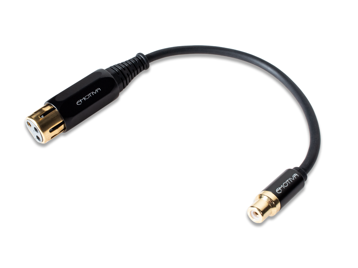
Balanced XLR to Unbalanced RCA Adapter Interconnect
The XLR to RCA Adapter delivers excellent electrical performance and protects the integrity of the audio signal in a slim, flexible cable. Shop online today!emotiva.com
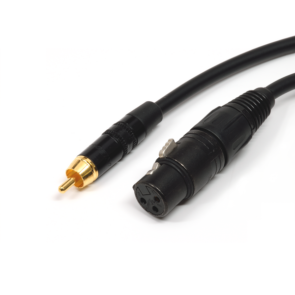
Benchmark XLRF to RCA Adapter Cable for Analog Audio - pin 3 floating
Benchmark Studio&Stage™ Analog XLR Cables CABLES ARE SOLD INDIVIDUALLY Price is for one cable, order 2 for a stereo pair. Hand assembled in the USA with true silver solder Benchmark Studio&Stage™ Analog XLR Cables combine the best cable, connectors, and construction techniques in order to offer...benchmarkmedia.com
Yes, I fully agree.
For XLR-to-RCA conversion, providing that we have no ground loop issue, I too believe that Pin-3 floating (unconnected) would be the most suitable and safe way, even though we lose 6 dB gain as well as we miss possible cancellation of intrusion noises (which seldom happen in home HiFi audio situation). We can easily implement various measures for 6 dB recovery afterwards such as in preamp section and/or in active SPs.
Of course, the best setup/solution should be "as much balanced connections as possible" just like that I have been sticking in my multichannel multi-SP-driver multi-amplifier audio project; please refer here and here for my latest system setup. My post here for basics of amplifier selections would be also of your reference.
Last edited:
")