• WANTED: Happy members who like to discuss audio and other topics related to our interest. Desire to learn and share knowledge of science required. There are many reviews of audio hardware and expert members to help answer your questions. Click here to have your audio equipment measured for free!

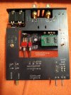
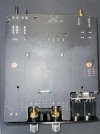
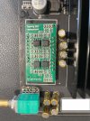
Topping PA5 fix - D01 Module Replacement for everyone

turion64

Member
Joined
Sep 22, 2020
Messages
16
Likes
20
No need to cut the pins actually. After removing the inside frame from the chassis just clean away the black coating from around the solder joints ( the black coating just gums up soldering tips badly in my experience). Use solderwick braid to remove most of the solder around each pin (don't overheat any area too long and let any area to mildly cool before continuing; patience is key). I then used a very low temperature melting solder (Chipquik removal alloy; only use a little) and worked it in each pin joint. It stay molten a long period of time so you actually run the soldering gun tip back and forth along the pins and it will eventually come right out. Then just clean up all the soldering pads with the solderwick braid & finally alcohol clean everything. Clear?

Cheers
 
OP
gamerpaddy

gamerpaddy

Member
Joined
Mar 6, 2022
Messages
69
Likes
320
Location
Germany
no they are soldered on both sides you rip traces when you try to pull it with force.
you either need a solder sucker / desoldering station or some low-melt solder / leades solder with hot air
 

giofala

New Member
Joined
May 4, 2022
Messages
4
Likes
4
Thank you for the help :)

I used just a basic soldering station, solderwick braid and a pump, with no success, so I've to buy something:

Immagine WhatsApp 2023-09-27 ore 09.43.31.jpg


Maybe this is enough? Heated Desoldering Pump

Or do I go for this quite expensive ChipQuik?

Or I can buy a cheap Hot Air Soldering Station?
 
OP
gamerpaddy

gamerpaddy

Member
Joined
Mar 6, 2022
Messages
69
Likes
320
Location
Germany
a pump should work
if you mean this by pump https://www.amazon.it/Aluminum-Desoldering-Suction-Soldering-Desolder/dp/B09PJKDY92/ref=sr_1_5?__mk_it_IT=ÅMÅŽÕÑ&crid=2O8UMAJC88TLK&keywords=desolder+tool&qid=1695801818&s=tools&sprefix=desolder+tool,diy,74&sr=1-5

add leaded solder or low melt solder, let it flow in to mix with the stuff thats in there then suck it out. mulitple times
wiggle the pins a little, sometimes they are stuck at the inner wall when theres no solder in the gap anymore

you might also need to preheat the whole board, pins 3 and 6 on the left are ground pins, they basically have the whole board connected to them to sink heat into. when its cold, its basically impossible to melt solder in them.
when you add leaded or low melt solder to the pins you could just pull out the module once it reaches its melting point

you could even preheat the board on a cookstove (ideally ceran, infrared not gas....) or a strong construction site halogen lamp

im using a desoldering station for this, a cheap one nothing special, set at 350°C, it comes out quite easily with leaded solder.
 

giofala

New Member
Joined
May 4, 2022
Messages
4
Likes
4
Thank you for the video @MCH :) For two rows of pin I'd need a second soldering station. I tried with one row, but doesn't worked, because there was not enough heat. Maybe it depends on the ground pins connected to the whole board (as @gamerpaddy told).

I bought an electric solder sucker pump on Amazon

61ONirBemkL._SX522_.jpg

If it doesn't work I'll go for a desoldering station
 
  • Like
Reactions: MCH

turion64

Member
Joined
Sep 22, 2020
Messages
16
Likes
20
Giofala: you've done a great initial removal step. I just melt the chipquik into each pin (after removing as much of the original solder as possible; a desoldering station can be used for the initial process) but I then leave the chipquik there through the rest of the removal process. Adding flux helps. The idea is to try to get it to blend with the original solder that is in the pin's mounting hole AND into the solder that's under the module, the solder you can't see. Once it gets blended in you can run the soldering iron up & down all the pins and the solder+chipquik combo will stay liquid long enough that the module should be able to be removed with gentle pulling. Ground pins will always need a bit more heat but using a slightly larger chisel tip will always allow greater heat transfer for component removal. One then just has to clean up the pads using solderwick & alcohol. I wish you success.
 
OP
gamerpaddy

gamerpaddy

Member
Joined
Mar 6, 2022
Messages
69
Likes
320
Location
Germany
For those who damaged their board by improperly desoldering the old module, like rippping traces and pads, i made a diagram that shows what connections to check.
just use a multimeter set to continuity mode, for example if A2 to A2 wont beep, you ripped a trace. just run a jumper wire between them.

IMG_20230929_025626.jpg
 

giofala

New Member
Joined
May 4, 2022
Messages
4
Likes
4
SUCCESS!!! :cool::cool::cool:

Thank you to everyone and special thanks to @gamerpaddy for his great work and great help. The last picture with all connections to test is very useful and should make anyone confident in fixing the PA5.

It turned out that I ripped off pads 7 and 8 for the rush (see picture below), now connected externally.

I think that all dummies like me can try to fix the PA5, I only recommend to be patient while desoldering and use the electric pump showed in a previous post, if you don't have a desoldering station.

Is it possible that the sound now is better than when it was new? Probably my original D-01 was defective already :D


IMG-20230928-WA0011.jpg
 

howard416

Active Member
Joined
Sep 12, 2019
Messages
255
Likes
144
Out of curiosity, anyone know how much voltage gain this little module makes?
 

turion64

Member
Joined
Sep 22, 2020
Messages
16
Likes
20
To any of the folk who have by-passed the volume control (to make it a straight amp) are the pins jumpered just directly across from one side to the other of the pot? The odd pin out must be a grounding pin I'm presuming.

Thanks,

Pete
 

Eldus

Active Member
Joined
Jun 8, 2021
Messages
133
Likes
115
I wonder if these modules measure differently than the stock one.
 

antcollinet

Master Contributor
Forum Donor
Joined
Sep 4, 2021
Messages
7,744
Likes
13,068
Location
UK/Cheshire
I wonder if these modules measure differently than the stock one.
No particular reason they should, apart from component tolerances. They are the same circuit.
 

restorer-john

Grand Contributor
Joined
Mar 1, 2018
Messages
12,727
Likes
38,928
Location
Gold Coast, Queensland, Australia
Maybe this trick works for you?

The copper wire method is fabulous for those impossible jobs with multilayer boards, as long as you use plenty of solder/flux and a powerful iron.

A good desoldering station flux/new solder, a careful hand and the preparedness to cut the legs when you need to (i.e. put your pride aside and cut the legs- pull them out individually afterwards) is what you need. Don't underestimate wick, it can pull solder out of places suction won't sometimes. All the tools in your arsenal are sometimes needed.

Just resist the tempation to crank the heat and pull- you'll wreck the board.

I've never damaged a multilayer, but I have been doing it for way too long. I have pulled the odd via out of double sided- I'd be lying if I said I hadn't. :)
 
Last edited:

Mr. Wax

Member
Joined
Mar 11, 2020
Messages
6
Likes
1
Hello everyone,

First of, thank you @gamerpaddy for coming up with a fix.

I did follow the instruction and ordered a single-side PCB. For the op-amps, I have sourced them locally in Canada as they were unavailable at JLCPCB.

I have brought the PCB and op-amps to my local electronic repair shop, along with the instructions provided on this forum.

He was able to remove the D01 module, install the new PCB (single-sided) and the op-amps.

The right side plays flawlessly, however the left side plays much quieter and is distorted.

I was wondering if anyone had a similar issue or would like to venture on a guess on where the problem might be coming from.

n.b.: my local repair man isn't doing troubleshooting on the entire unit, unless I would point him in the right direction first.
 
OP
gamerpaddy

gamerpaddy

Member
Joined
Mar 6, 2022
Messages
69
Likes
320
Location
Germany
he must have made a mistake or missed a solder joint. both channels are built identical.
maybe ripped a trace when desoldering the old module.

see https://www.audiosciencereview.com/...e-replacement-for-everyone.44219/post-1729797
if he ripped a trace, it can be found this way.
otherwise theres a misplaced component on the pcb or a dead on arrival opamp.
sometimes ungrounded soldering irons can damage components. and opamps are very sensitive to this.
can you show me a picture of what the pcb looks like?
 

Mr. Wax

Member
Joined
Mar 11, 2020
Messages
6
Likes
1
he must have made a mistake or missed a solder joint. both channels are built identical.
maybe ripped a trace when desoldering the old module.

see https://www.audiosciencereview.com/...e-replacement-for-everyone.44219/post-1729797
if he ripped a trace, it can be found this way.
otherwise theres a misplaced component on the pcb or a dead on arrival opamp.
sometimes ungrounded soldering irons can damage components. and opamps are very sensitive to this.
can you show me a picture of what the pcb looks like?
Thank you so much for your reply.

I spoke to the repair man and he said to have used a grounded soldering iron and has tested all traces and double-checked the op-amps soldering joints.

That would leave a two options : (1) a misplaced component on the PCB (which I believe you can confirm with the attached pictures) or (2) DOA op-amp(s).

Please see the attached pictures. I did my best to have the clearest picture. Do let me know if you need more.

Thanks!
 

Attachments

  • 3.jpg
    3.jpg
    310.1 KB · Views: 55
  • 2.jpg
    2.jpg
    357.6 KB · Views: 53
  • 1.jpg
    1.jpg
    340.6 KB · Views: 59
OP
gamerpaddy

gamerpaddy

Member
Joined
Mar 6, 2022
Messages
69
Likes
320
Location
Germany
1701370532452.png

this opamp looks different
there should be two NE5532 and two OPA1612 but even mixed up they should work unless one is dead on arrival or died while working on it.

cant read component values but they seem to be placed by the chinese fab anyways, look good to me.

solder joint on the left header #3 and 4 looks like too little solder but should still have a connection.
he seems to use bad solder, it doesnt flow well. small spikes on the top. either he has its soldering iron set too high causing the flux to burn off too quickly or bad solder.

and top left op amp fifth (bottom left) leg looks suspicious.


problem is, there are traces ontop of the pcb too. and if he didnt properly remove all the old solder when trying to pull out the module, it rips them off the board.
the only way to see if its the case, is to measure the points i mentioned
 

Mr. Wax

Member
Joined
Mar 11, 2020
Messages
6
Likes
1
View attachment 330676
this opamp looks different
there should be two NE5532 and two OPA1612 but even mixed up they should work unless one is dead on arrival or died while working on it.

cant read component values but they seem to be placed by the chinese fab anyways, look good to me.

solder joint on the left header #3 and 4 looks like too little solder but should still have a connection.
he seems to use bad solder, it doesnt flow well. small spikes on the top. either he has its soldering iron set too high causing the flux to burn off too quickly or bad solder.

and top left op amp fifth (bottom left) leg looks suspicious.


problem is, there are traces ontop of the pcb too. and if he didnt properly remove all the old solder when trying to pull out the module, it rips them off the board.
the only way to see if its the case, is to measure the points i mentioned

I have tested all the connection points from the post you have provided, and they all worked.

I was able to take better close-up shots of the PCB:
1- The op-amp model numbers appear to match, except for the suffix "A2T2G4" and "A2RNG4" on the NE5532 op-amp. Does it matter?
2- Could you please have another look at the legs and the placement from the fab?

If everything else looks fine, what would you suggest my next steps be? Re-order a set of op-amps and re-install a new PCB (JLCPCB has sent me 5 anyways)?

Again, very grateful for your help. Thanks a million!
 

Attachments

  • 1.jpg
    1.jpg
    286.1 KB · Views: 41
  • 2.jpg
    2.jpg
    223.1 KB · Views: 47
Last edited:
OP
gamerpaddy

gamerpaddy

Member
Joined
Mar 6, 2022
Messages
69
Likes
320
Location
Germany
which channel is faulty?
if its the left one.. this pin doesnt seem to be soldered to the pad below. try poking it with a wooden toothpick while the amp is turned on and hear if the problem goes away.
GrGb46y.png
 
Top Bottom