So I designed, ordered and paid the double-sided PCB with metal through-holes and top shielding ground plane.
View attachment 44452
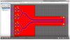
Fig.16. New test circuit that comprises 86dB noise gain/-1 signal gain circuit and also 40dB signal gain circuit, for dual opamps.
View attachment 44453
Fig.17. And this is the photo of the new test circuit
You might want to consider stitching those top/bottom copper pours together with vias...
Typical RF design with lots of vias:
The tool I use (Altium) has a via stitching function that will create an array of vias. It can also generate via walls for GBCPW (ground-backed coplanar waveguide [ which is what you fabbed minus the vias)
Kicad has a cool via fence tool for co-planar waveguides
the "oh so cool" music thing kinda sucks... I hate vids with that.
It might also be that using SMT components will allow a lower profile and reduce the EMI profile of the more critical parts of your test setup.
Interesting paper on RF isolation and EMI :
https://core.ac.uk/download/pdf/84312564.pdf
Where :
"The highest isolation seen in this study was achieved with stripline structures. ... Stripline provides approximately 20dB better isolation over GBCPW under the same layout conditions."
I do a lot of commercial analog designs for ICRI and mil applications and have very little issues with susceptibility; unless I do stoopid (which I'm really good at). Emissions... conducted as well as radiated ... well, see my other posts on that. That can be nightmare, esp for MIL-STD-461 where you need to be below 24dBuV...
For silly sensitive applications, we use guard rings around opamps for applications like medical gear and things like strain gauges, where the output of the device feeding the opamp is low amplitude and a higher impedance.
Another issue is Seebeck voltages that can be caused by thermoelectric voltages
See the AD App Notes:
https://www.analog.com/en/technical-articles/layout-for-precision-op-amps.html#
www.analog.com/media/en/technical-documentation/data-sheets/AD8551_8552_8554.pdf
I've only had a few instances where I had to deal with thermoelectric issues and these were silly sensitive topologies that had little room for output error... nothing that an audio product would ever deal with.
Another appnote from TI on using opamps for lower EMI susceptibility:
www.ti.com/lit/slyt660
There's also the section in Chapter 11 of the AD book Basic Linear Design Guide - Section 11.3:
ftp://ftp.analog.com/pub/cftl/ADI%20Classics/Basic%20Linear%20Design%20(Linear%20Circuit%20Design%20Handbook),%202007/Chapter_11_Overvoltage_Effects_on_Analog_Integrated_Circuits.pdf

")