• WANTED: Happy members who like to discuss audio and other topics related to our interest. Desire to learn and share knowledge of science required. There are many reviews of audio hardware and expert members to help answer your questions. Click here to have your audio equipment measured for free!

Sensitivity of opamps to air coupled EM fields, especially of the LM4562/LME497X0 family

JohnYang1997

Master Contributor
Technical Expert
Audio Company
Joined
Dec 28, 2018
Messages
7,175
Likes
18,298
Location
China
That's the issue with the attitude. Manufacturer or companies that produce and are trying to sell products will certainly think differently than enthusiasts, hobbiests.
After seeing many of his posts, I am understanding.
It's not like holy shit we found a hole in design, it's going to be end of the world, no one should use it. But rather, taking a small thing that happens to surface to let us talk about it. And then by understanding what it is, we learn. And by the severeness/important of the matter, we decide whether to take consideration in the future. In this case it is certain a problem someone can face, even though it's small it is. Using high gain is just a method to focus and magnify the issue.
We are always defensive seeing a small issue brought to the surface. Instead, we should comprehend and try to take in as much as we can before we make comments.
Just answer this question yourself: Does eliminating this make a better design. If it is even by a tiny bit, it's constructive and helpful.
We just don't have to push it to every measurements to design. Because there are always aspects that are more important than these.
 

restorer-john

Grand Contributor
Joined
Mar 1, 2018
Messages
12,680
Likes
38,784
Location
Gold Coast, Queensland, Australia
That's the issue with the attitude. Manufacturer or companies that produce and are trying to sell products will certainly think differently than enthusiasts, hobbiests.
After seeing many of his posts, I am understanding.
It's not like holy shit we found a hole in design, it's going to be end of the world, no one should use it. But rather, taking a small thing that happens to surface to let us talk about it. And then by understanding what it is, we learn. And by the severeness/important of the matter, we decide whether to take consideration in the future. In this case it is certain a problem someone can face, even though it's small it is. Using high gain is just a method to focus and magnify the issue.
We are always defensive seeing a small issue brought to the surface. Instead, we should comprehend and try to take in as much as we can before we make comments.
Just answer this question yourself: Does eliminating this make a better design. If it is even by a tiny bit, it's constructive and helpful.
We just don't have to push it to every measurements to design. Because there are always aspects that are more important than these.

Well said.
 

SIY

Grand Contributor
Technical Expert
Joined
Apr 6, 2018
Messages
10,486
Likes
25,242
Location
Alfred, NY
Be careful not to conflate "high gain" with "high noise gain." The latter is the issue with trying to extrapolate this test setup to actual audio circuits.
 

March Audio

Master Contributor
Audio Company
Joined
Mar 1, 2016
Messages
6,378
Likes
9,319
Location
Albany Western Australia
Be careful not to conflate "high gain" with "high noise gain." The latter is the issue with trying to extrapolate this test setup to actual audio circuits.
This.

Inappropriate tests don't provide us with useful information. This issue of EM sensitivity is very well known about, it's nothing new and has mitigations. So if it doesn't manifest in normal audio circuit design what's all the shouting about?
 
Last edited:

SIY

Grand Contributor
Technical Expert
Joined
Apr 6, 2018
Messages
10,486
Likes
25,242
Location
Alfred, NY
This. Inappropriate tests don't provide us with useful information. This issue of EM sensitivity is very well known about, it's nothing new. So if it doesn't manifest in normal audio circuit design what's all the shouting about?

That test circuit is designed to measure open loop gain linearity. So it's an appropriate test for that. I have to admit I've never seen this circuit used for determination of EMI susceptibility, nor does that make any sense to me (but I caveat that by my usual "I am not an engineer" disclaimer).

Sources for some info on EM immunity testing and design:

http://www.ti.com/lit/an/sboa128a/sboa128a.pdf
https://www.analog.com/media/en/training-seminars/tutorials/MT-096.pdf
 

mansr

Major Contributor
Joined
Oct 5, 2018
Messages
4,685
Likes
10,703
Location
Hampshire
This. Inappropriate tests don't provide us with useful information. This issue of EM sensitivity is very well known about, it's nothing new and has mitigations. So if it doesn't manifest in normal audio circuit design what's all the shouting about?
It all feels a bit like a crusade. If abnormal EMI sensitivity was a common problem in actual products using these chips, that would be useful to point out.
 

weme

Member
Joined
Mar 2, 2021
Messages
70
Likes
63
Location
Germany
Sensitivity of opamps to air coupled EM fields, especially of the LM4562/LME497XY family
Your comments are welcome, but please let me not to reply the questions that are already covered in this text, it was an exhausting job.
Just an idea to narrow down the problem:

Create three different layouts: measure and compare.

Minimising Input Errors
Walter Jung, ELECTRONIC DESIGN, DECEMBER 14, 1998
http://waltjung.org/PDFs/WTnT_Op_Amp_Audio_4.pdf
->
http://web.archive.org/web/20100815102309/waltjung.org/PDFs/WTnT_Op_Amp_Audio_4.pdf
 

mediatechnology

New Member
Joined
Dec 18, 2018
Messages
2
Likes
5
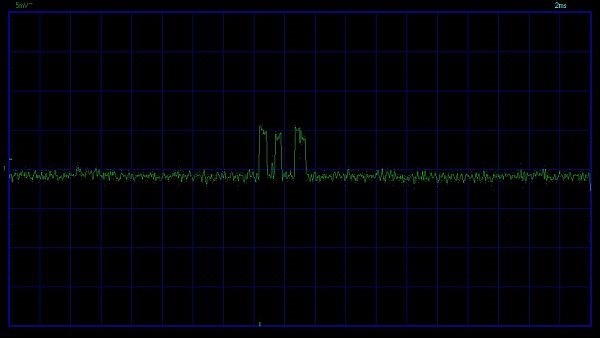
I've had the same EMI issues with the LME49720. The '49720 makes a good RF envelope detector.


They're also prone to burst noise:


This is one sample I captured.

LME49720_5F00_Noise.jpg


And if the circuit impedances are too high the LM4563/LME49720 latch up. This was written in response to a TI e2e poster trying to use the LME49720 like a FET input in a guitar instrument input.


I've never seen the EMI issue with a common NJM5532. I avoid the LME49720 because it has too many warts.
 

audio2design

Major Contributor
Joined
Nov 29, 2020
Messages
1,769
Likes
1,830
@pma Late to the party and dumb question, so I apologize in advance, but the LM4562 is a dual, the AD797 / LT1028 are singles, the power pins are different (7 is power in singles, 8 is power on doubles). Did you have two different PCB for your original test?

When testing the single op-amp in a dual package, what did you do with the other op-amp? I don't see any scope traces of both outputs at the same time.

Radiated or capacitively coupled EMI is pretty much always at the source frequency, i.e. 50Hz, but you have spurs at 2x, which as others have noted is typically power supply. If your other op-amp was oscillating or similar, it could have been "rough" on the power supply and/or generated die level interaction at the power supply frequency.
 
OP
pma

pma

Major Contributor
Joined
Feb 23, 2019
Messages
4,602
Likes
10,769
Location
Prague
@pma Late to the party and dumb question, so I apologize in advance, but the LM4562 is a dual, the AD797 / LT1028 are singles, the power pins are different (7 is power in singles, 8 is power on doubles). Did you have two different PCB for your original test?

When testing the single op-amp in a dual package, what did you do with the other op-amp? I don't see any scope traces of both outputs at the same time.

Radiated or capacitively coupled EMI is pretty much always at the source frequency, i.e. 50Hz, but you have spurs at 2x, which as others have noted is typically power supply. If your other op-amp was oscillating or similar, it could have been "rough" on the power supply and/or generated die level interaction at the power supply frequency.

Thank you for your post and I hope you do not assume that I do not know which opamps are dual and which are single. The tests were performed in a period of about 14 years with several different PCB boards, metal boxes etc. The results have been consistent. Mains frequency is not an issue, even the boards supplied from batteries behaved same. Most probably it is rather about something coming from USB.

Below you can se TI eval. board used and one of my boards. The inputs of unused opamp halves were shorted in case of dual units.

Please take this as my last post on this topic, it is time consuming to dig out plots and photos from old archives.

47920_eval_schematics.png


49720_eval_board.JPG


49720_test_board.JPG
 

eliash

Senior Member
Joined
May 29, 2019
Messages
408
Likes
209
Location
Bavaria, near lake Ammersee
Stumbled across this thread searching some other opamp information. Browsing the previous pages, me personally haven't seen any RF wideband measurements on these LF design applications here. A measurement which could bring some light into the case is to hook up a spectrum analyser up to 1-3GHz ,while this spurious noise is present...eventually the opamp is oscillating for some reason and doing "homodyne demod".

I liked the 497x0 series before I read about its rather poor common mode distortion behaviour (as a voltage follower), so I switched to OPA211 just for the sake of reducing D2 a bit more (...that was the reason, if I remember correct...).
Anyway the well sounding audio preamp circuit, where it went into, immediately revealed some (even sub-) millivolt DC output flicker when the AC-coupled! volume pot was set to zero or close - probably HF-oscillation, but almost nothing audible. Experimentation brought me to the solution to block the non-inverting input with >=22pF, flicker gone- safely! Similar situation in a self-designed filter circuit, completely different layout, but long (70cm) shielded cable and 220Ohms in series (the OPA211 doesn't like low inductance on non-inverting input), same story...bet it was oscillating at several hundred MHz..
 
Top Bottom