• WANTED: Happy members who like to discuss audio and other topics related to our interest. Desire to learn and share knowledge of science required. There are many reviews of audio hardware and expert members to help answer your questions. Click here to have your audio equipment measured for free!

Review and Measurements of Yamaha RX-A1080 AVR

OP
amirm

amirm

Founder/Admin
Staff Member
CFO (Chief Fun Officer)
Joined
Feb 13, 2016
Messages
44,699
Likes
241,387
Location
Seattle Area
Back in the day, multiple transformers, multiple tappings and regulated PSUs were used if the product was a single box. I've got preamplifiers with three transformers- one for each channel and one for the control circuitry. I've got a TOTL D/A converter with 3 toroidal power transformers and goodness knows how many individual regulated rails.
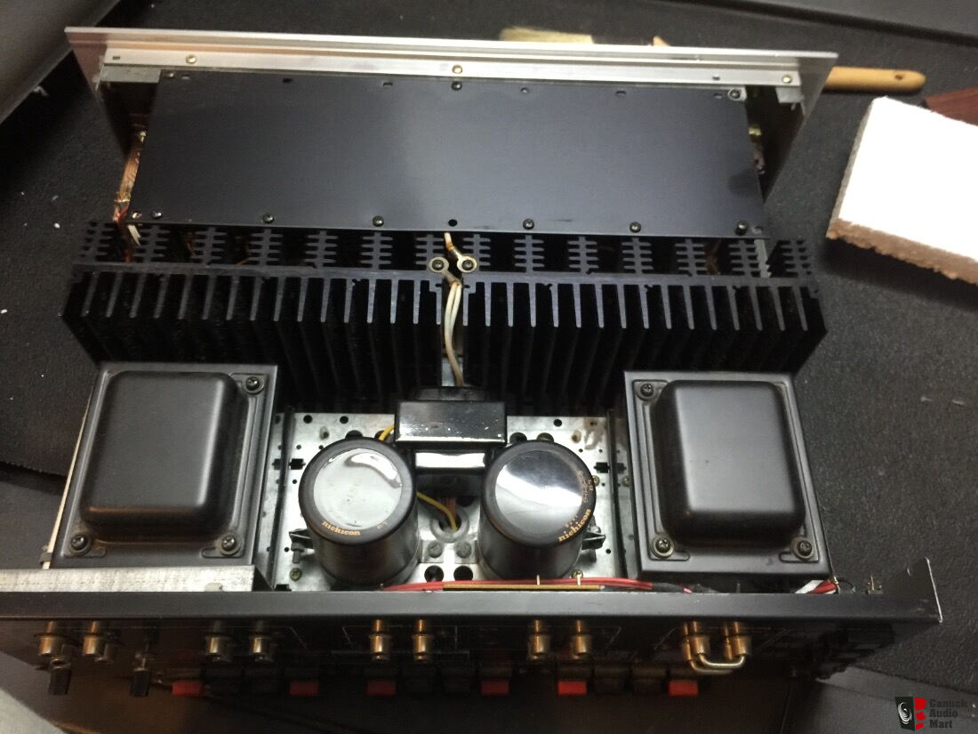
I still have my Optonica amplifier with three transformers. One for low voltage one dedicated to each power amp. It looks like this:

1309911-osm4646-integrated-st3636-tuner.jpg


Maybe I should test it!
 

restorer-john

Grand Contributor
Joined
Mar 1, 2018
Messages
12,734
Likes
38,968
Location
Gold Coast, Queensland, Australia
Maybe I should test it!

Looks like the 4646?

1569286225660.png


The PSU caps are dual caps in a single can.

Dig it out, blow out the cobwebs, give the pots and switches a clean and cycle them a few times, then throw it on the bench!

That will be a fun review! :)
 
OP
amirm

amirm

Founder/Admin
Staff Member
CFO (Chief Fun Officer)
Joined
Feb 13, 2016
Messages
44,699
Likes
241,387
Location
Seattle Area
Ah, I had forgotten that they used to list the number of key components:

1569286767074.png


Used to love reading how many transistors they had in them! Oh, the fun old days....
 

GrimSurfer

Major Contributor
Joined
May 25, 2019
Messages
1,238
Likes
1,484
The review would likely show greater THD+N, lower damping, and much lower power output than the majority of today's bargain basement amps. But that would be missing the point.

PS-related limitations and noise would be far less than a great many of today's amps [26,000 uF of power caps for 2x60 WPC). It's high current output would be rock steady down to nearly dead-short impedances. It's temperature stability would go on and on forever.

Great advances have been made in circuit design over the past 30-40 years. These have corresponded with voluntary losses in power supply and thermal management capacity. So while time has increased what the SOTA can provide, the limitations have been imposed to knock out products at lower and lower cost.

Why? Because when the boardroom discussion takes place on whether to make something better or more profitable takes place, profit wins.
 
Last edited:

restorer-john

Grand Contributor
Joined
Mar 1, 2018
Messages
12,734
Likes
38,968
Location
Gold Coast, Queensland, Australia
It's high current output would be rock steady down to nearly dead-short impedances. It's temperature stability would go on and on forever.

The issue is not the power supply, it's the Sanken S-100W Darlington packs used for the power amplifiers. They will be the limiting factor and at 40+ years old, I'd be limiting the testing to 8 ohms continuous and 4 ohms burst/short term only.

1569290364343.png


They are completly unobtainium as spare parts unless @DonH56 still has a some in his shed. :)

https://www.audiosciencereview.com/...-of-march-audio-dac1.5755/page-12#post-129399
 

DonH56

Master Contributor
Technical Expert
Forum Donor
Joined
Mar 15, 2016
Messages
7,912
Likes
16,744
Location
Monument, CO
The issue is not the power supply, it's the Sanken S-100W Darlington packs used for the power amplifiers. They will be the limiting factor and at 40+ years old, I'd be limiting the testing to 8 ohms continuous and 4 ohms burst/short term only.

View attachment 34324

They are completly unobtainium as spare parts unless @DonH56 still has a some in his shed. :)

https://www.audiosciencereview.com/...-of-march-audio-dac1.5755/page-12#post-129399

No comment. (OK, I might have a few of the S-50, but pretty sure all the S-100's are gone. And given that my parts are now stored in an on-site black hole, finding them would be challenging. ;) )
 

scooter

Active Member
Forum Donor
Joined
May 12, 2019
Messages
139
Likes
51
No, "lesser number of drivers" does not mean "more impedance" and "less stress". You'd have to look at the impedance curve of your speakers to estimate the impedance -- it changes over frequency. Further more, if your speaker was an ideal 8-ohm load at all frequencies, then when you split the bass and treble then each amp still sees 8 ohms.
I agree and understand that each driver impedance changes across a frequency spectrum, but given the fact that normally all drives are connected in parallel to each other, this means that electrical resistance will be always less than if they were split. At a given moment and specific frequency all drivers will have different impedance, but if we further connect them in parallel the "final" impedance will be always less than of that driver before with the smallest impedance.
If we imagine woofer as 2KW electrical heater at home and tweeter as 5W LED lamp, heater is already plugged in receptacle and later we plug LED lamp too, this will decrease common resistance seen by the source network which in this scenario can be 1 amplifier... The same must apply for the audio at a given frequency and time.
You do say that impedance on final speaker terminals will be the same as if woofers and midrange/twitters were split? Or am i mistaken?
 

DonH56

Master Contributor
Technical Expert
Forum Donor
Joined
Mar 15, 2016
Messages
7,912
Likes
16,744
Location
Monument, CO
I agree and understand that each driver impedance changes across a frequency spectrum, but given the fact that normally all drives are connected in parallel to each other, this means that electrical resistance will be always less than if they were split. At a given moment and specific frequency all drivers will have different impedance, but if we further connect them in parallel the "final" impedance will be always less than of that driver before with the smallest impedance.
If we imagine woofer as 2KW electrical heater at home and tweeter as 5W LED lamp, heater is already plugged in receptacle and later we plug LED lamp too, this will decrease common resistance seen by the source network which in this scenario can be 1 amplifier... The same must apply for the audio at a given frequency and time.
You do say that impedance on final speaker terminals will be the same as if woofers and midrange/twitters were split? Or am i mistaken?

The drivers are not in parallel; there is a crossover from the terminals on the way to the drivers. And impedance also depends upon the enclosure and how acoustic loading is impressed upon the driver; it is an electromechanical system so just measuring the driver and/or crossover in isolation will not in general provide the same impedance curve as the complete speaker.

By splitting the crossover you will affect the impedance each amplifier sees but that does not mean it is always higher. Draw a line at some frequency in the speaker impedance plots above and you can sort of envision what the bass and treble impedance looks like to the amplifiers. The difference is the impedance will usually go up for frequencies outside the frequency range of the part you are driving; within the frequency band of the crossover you are driving, it should not change. The principle in network theory is superposition; the crossover is a simple linear circuit and splitting it apart does not change its fundamental properties.

In the picture below you can see the effect of the crossover. For this very simple example, a high-pass filter (HPF) is before the tweeter, and low-pass filter (LPF) before the woofer, providing the desired frequency response. The impedance of each crossover+ speaker is 8 ohms just to provide a simple example. If you short the input terminals, the amplifier sees the total circuit of crossover plus speakers, and we get a flat frequency response and impedance. (The real world is not so pretty but this is just an example.) If you separate the terminals for bi-amping, then below the tweeter's frequency range, the crossover blocks all LF signals to the tweeter. Now the tweeter terminals look like an open to the amplifier at low frequencies. Similarly, signals above the woofer's frequency range are blocked by the LPF, so high frequencies see an "open" when driving the woofer terminals. Except right at the crossover region they are never really in parallel, and the crossover is rolling off in each direction so ideally the impedance is flat when both terminals are driven (shorted).

1569334042363.png


HTH - Don

Edit: This is waaay outside the topic; perhaps best pursued in another thread.
 
Last edited:

scooter

Active Member
Forum Donor
Joined
May 12, 2019
Messages
139
Likes
51
Hope Amir will forgive me for another off topic post :)
What you have described is indeed true but applies only if we were playing just a single tone with definite and constant frequency, which could be blocked or passed by the crossover elements. But music is a complex mix of all various frequencies, vocals, instruments, etc... This means that mostly none of the drivers are fully "blocked" by crossover during a playback, there will be a simultaneous hit in on the drums, screaming vocals and upper frequencies, meaning that during those moments woofer, midrange and tweeter drivers will be "open" to output terminals, where they're connected in parallel and summing their impedance. So if only one amplifier is used, it has to deal with all of them together, whereas individual ones could easily drive only part of the frequency spectrum assigned to them.
This again brings me back to my original post where I stated that Yamaha lies in their statement that AVR has individual amplifiers and there will be a major improvement in audio quality.
Quote from Yamaha manual:
"Using the four internal amplifiers for front speakers allows you to have more high quality sounds.
For example, you can use 2-way bi-amp speakers with a woofer and tweeter for front speakers. It produces expansive sound in a bi-amp system featuring a woofer and tweeter. By directly driving each speaker individually, it produces powerful sound while maintaining the feeling of a high S/N ratio".

Thanks
 

blueone

Major Contributor
Forum Donor
Joined
May 11, 2019
Messages
1,195
Likes
1,547
Location
USA
"...the feeling of high S/N ratio." Really? Weird.
 

DonH56

Master Contributor
Technical Expert
Forum Donor
Joined
Mar 15, 2016
Messages
7,912
Likes
16,744
Location
Monument, CO
Hope Amir will forgive me for another off topic post :)
What you have described is indeed true but applies only if we were playing just a single tone with definite and constant frequency, which could be blocked or passed by the crossover elements. But music is a complex mix of all various frequencies, vocals, instruments, etc... This means that mostly none of the drivers are fully "blocked" by crossover during a playback, there will be a simultaneous hit in on the drums, screaming vocals and upper frequencies, meaning that during those moments woofer, midrange and tweeter drivers will be "open" to output terminals, where they're connected in parallel and summing their impedance. So if only one amplifier is used, it has to deal with all of them together, whereas individual ones could easily drive only part of the frequency spectrum assigned to them.
This again brings me back to my original post where I stated that Yamaha lies in their statement that AVR has individual amplifiers and there will be a major improvement in audio quality.
Quote from Yamaha manual:
"Using the four internal amplifiers for front speakers allows you to have more high quality sounds.
For example, you can use 2-way bi-amp speakers with a woofer and tweeter for front speakers. It produces expansive sound in a bi-amp system featuring a woofer and tweeter. By directly driving each speaker individually, it produces powerful sound while maintaining the feeling of a high S/N ratio".

Thanks

The circuits are the same if you apply broadband noise, music, or single tone. The crossover will pass frequencies appropriate for the respective driver, and block the rest. And again, the issue with an AVR is that each amplifier has the same full-range input signal applied, so even if power output is less per amplifier when bi-amped, the voltage is the same, so there is not a significant increase in headroom because the amplifiers are voltage-limited (as well as current limited if that happens to be the case). The power supply rails will sag the same, or maybe a little worse when bi-amping compared to using a single channel. Current delivery will be improved, however, for the individual amplifiers (again up to the limitations of the power supply).

Note this is not true for conventional (to me) bi-amping where the crossover is moved before the amplifier instead of afterwards.

You said Yamaha lied about having individual amplifiers. That is not a lie. They are all individual amplifiers, but driven from the same signal when bi-amping is used, and using the same power supply. Separate, individual amplifiers, but sharing input signal and power supply thus they are not necessarily completely independent when viewed from a high level.

I have never contended there will be an improvement in sound quality; except under special circumstances I would would expect no change (good or bad) in sound quality. The quote from Yamaha sounds like something written by Marketing and not Engineering.

You have said you already know every point I have made; I'll step out of this as it is taking too much time to explain what you already know and/or have decided to believe on your own, and I feel like we are talking (posting) past each other. I don't know what you want.
 

Willem

Major Contributor
Joined
Jan 8, 2019
Messages
3,730
Likes
5,360
So sad to see these disappointing measurements when Yamaha does so well with their AS501/701/801 budget stereo amplifiers.
 

scooter

Active Member
Forum Donor
Joined
May 12, 2019
Messages
139
Likes
51
You have said you already know every point I have made; I'll step out of this as it is taking too much time to explain what you already know and/or have decided to believe on your own, and I feel like we are talking (posting) past each other. I don't know what you want.
I just want truth to be told :)
This discussion started when I said there will be a less stress on each amplifier when supplying individual drivers due to a more impedance of them, you said an opposite of it. So I got interested, maybe I was wrong... But yet I haven't received detailed answer for it. It wasn't about the common external power available to all 7 channels, and how it will sag in the same way before or after biamping, it was about to distinguish whether an impedance stays the same for a "single" amplifier when drivers are split.
Seems like I'm believing on my own.
 

Willem

Major Contributor
Joined
Jan 8, 2019
Messages
3,730
Likes
5,360

GTsmokeya84

Member
Forum Donor
Joined
May 3, 2019
Messages
44
Likes
41
Location
Chicago Burbs
I have this exact model and while I do not do any serious listening on it I am not surprised. I use this unit for my loft and its strictly for movies or tv and some video games. I had picked up a slightly cheaper Denon before this unit but it sounded flat and hollow compared to my older Harmon Kardon I replaced, than within 2 hours it went into protection mode and I packed it up and said shame on me for being cheap.

Its a shame as so many people like Denon and I had recommended one to a friend maybe 2 years ago and he had nothing but HDMI problems and compatibility issues, so my back up for him was an Onkyo and he still has it working just fine.
 

Ataraxia

Active Member
Joined
Sep 22, 2019
Messages
136
Likes
76
Upgraditis is most profound when the listener feels (or hears) something is missing. So before trying to determine your needs, perhaps you could share with us an explanation of your needs and what you feel is currently missing...

Which integrated with room correction are you referring to? If it is the Lyngorf TDAI-2170, I thought Amir reviewed it and it did not measure too well. Whether you can hear the difference between an AVR, integrated amp (there are many, so which one?), or separate preamp/power amp or not, the KEF R3 probably deserve something better than an AVR. Some integrated amps could be just adapted from their AVR cousins, so just be careful if that's an issue for you.

This is not the best snapshot because I was new at REW and did not know the optimal way to set the freq range and save a REW photo but it shows the null I have around 100HZ. This null is there even with only R3's. So I think I'm missing some of what Dirac or Room Perfect would give. So for me it seems either Arcam Dirac or Lyngdorf Room Perfect might be a great next step in amplification. I might be happy with the R3's and good Dirac or Room Perfect amplification.

Next I believe I may be missing a more forward and detailed voicing of the speakers... R3's are excellent and transparent but I've read and heard online that for example Salk Silk's, or maybe even Reference 1's may be more of what I'm looking for. Or maybe try Ascend Sierra 2ex. I've heard they are more forward than R3's. I've heard R3's called "laid back." A tad more forward and detailed presentation, but still musical. Like Genelec but musical. I like detail.
 

Attachments

  • R3 Rythmik Flat.jpg
    R3 Rythmik Flat.jpg
    88.5 KB · Views: 226
  • R3 Only YPAO enabled.jpg
    R3 Only YPAO enabled.jpg
    68.3 KB · Views: 171
  • KEF R3.jpg
    KEF R3.jpg
    78.7 KB · Views: 173
  • R3 Only YPAO On FR.jpg
    R3 Only YPAO On FR.jpg
    74.1 KB · Views: 308
  • R3 Only YPAO On WF.jpg
    R3 Only YPAO On WF.jpg
    152.7 KB · Views: 249
  • R3Rythmik.jpg
    R3Rythmik.jpg
    540.7 KB · Views: 263
Last edited:

GrimSurfer

Major Contributor
Joined
May 25, 2019
Messages
1,238
Likes
1,484
Looks like a nice space. What are the room dimensions? I'm intrigued to run the numbers to see where the 100 Hz null is coming from...

Also, what is the crossover setting for those lovely dual subs?
 

Ataraxia

Active Member
Joined
Sep 22, 2019
Messages
136
Likes
76
Looks like a nice space. What are the room dimensions? I'm intrigued to run the numbers to see where the 100 Hz null is coming from...

Also, what is the crossover setting for those lovely dual subs?

Thanks. :) My WI apt for now, maybe moving back to a Cali apt soon with different dimensions... 13' x about 30' where the left side is open and right side boxed in.

So maybe the room dimensions and sub/speaker placement are the cause but the room will change in the future.

Using A2080 bass management set to 40 Hz crossover...

Below a REW sweep with A2080 crossover @ 120 HZ.
 

Attachments

  • Room.jpg
    Room.jpg
    450.9 KB · Views: 193
  • SpeakerPlacement.jpg
    SpeakerPlacement.jpg
    597.1 KB · Views: 177
  • Fromfrontdoor.jpg
    Fromfrontdoor.jpg
    286.7 KB · Views: 188
  • Sub Yamaha A2080 crossover 120 hz.png
    Sub Yamaha A2080 crossover 120 hz.png
    145.5 KB · Views: 211
Last edited:

GrimSurfer

Major Contributor
Joined
May 25, 2019
Messages
1,238
Likes
1,484
Here's a link to a calculator for determining eigenmodes.

https://www.hunecke.de/en/calculators/room-eigenmodes.html

When I run the rough numbers (guessed your ceiling height at 8 ft, used thumbnail conversions to meters) of your space, I do see the potential for a lot of activity in the 88-99 Hz range, the orientation of which would influence readings taken along the axial plane. Said another way, a 1-2 ft f/r adjustment of a calibrating microphone at the listening position could significantly affect the reading (as could reclining, leaning forward etc).

This calculator presents a somewhat different view:

http://www.mcsquared.com/modecalc.htm

The view shows mode frequencies, so you can interpolate the nulls that lie between them. Similarly, there seems to be potential for axial and tangential nulls in the ~90 Hz range. Depending on microphone placement, these could add up to as much as -9 dB (but that would take a fair amount of bad luck, IMHO).

You xo for your subs likely mean that your mains are the likely culprits responsible for generating 100 Hz node. (I base this on a 40 Hz xo point and a 12 dB/octave slope which would reduce sub output to negligible (though still reinforcing) levels at 100 Hz). That's too bad in a way because the mains need to straddle the longitudinal axis in order to create a sound stage. Have you tried toeing the mains in or out to see what effect that has on the null? (The effect very much depends on the dispersion pattern of the drivers... fortunately, your listening position is relatively close so you might be able to get away with a great deal of toe without shattering the sound stage.)

Nulls are a real PITA because you get into a catch-22 trying to reduce them (reducing spl at frequency will reduce the null but will also reduce the output at that frequency, so the suck-out persists). This is where room correction ends and the need for room treatment begins, IMHO.
 
Last edited:
Top Bottom