Now I wonder if it's possible to make distortion at 10khz to 0.0001% 10W 4ohm load.

-
WANTED: Happy members who like to discuss audio and other topics related to our interest. Desire to learn and share knowledge of science required. There are many reviews of audio hardware and expert members to help answer your questions. Click here to have your audio equipment measured for free!
- Forums
- Audio, Audio, Audio!
- Amplifiers, Phono preamp, and Analog Audio Review
- Stereo and Multichannel Amplifier Reviews
You are using an out of date browser. It may not display this or other websites correctly.
You should upgrade or use an alternative browser.
You should upgrade or use an alternative browser.
Review and Measurements of Benchmark AHB2 Amp
- Thread starter amirm
- Start date
orangejello
Active Member
- Joined
- Apr 18, 2019
- Messages
- 232
- Likes
- 354
Anyway, kudos for bringing the first "sane" RCA-out to XLR-in cable to market (that I know of). It really was about time. No idea why cable manufacturers have been showing precious little interest.
You can order these from Pro Audio LA. They are wired the same way as the Benchmark and cost half as much. Also you can have them made to whatever length you want and choose male or female for the XLR side.
RCA-XLRM-1RCA to XLR Male Cable | Made from Canare Quad L-4E6S, Neutrik Gold & Amphenol Gold Connectors
The Canare and Neutrik pieces are ubiquitous in studio application.
I ordered a pair and with shipping it was $50.
JP
Major Contributor
Mine arrived mid-week and I installed them Friday night and Saturday morning. I have to contact support as 1) the speakers pop when the muting circuit engages and disengages and 2) the 12V trigger doesn’t work consistently. If I try it out repeatedly it’ll work, but both times I listened for over an hour it didn’t work on power off. The first time I had to turn all three amps off separetaly, and the second time the second amp turned of the third. Disappointing.

Tks
Major Contributor
- Joined
- Apr 1, 2019
- Messages
- 3,221
- Likes
- 5,497
Mine arrived mid-week and I installed them Friday night and Saturday morning. I have to contact support as 1) the speakers pop when the muting circuit engages and disengages and 2) the 12V trigger doesn’t work consistently. If I try it out repeatedly it’ll work, but both times I listened for over an hour it didn’t work on power off. The first time I had to turn all three amps off separetaly, and the second time the second amp turned of the third. Disappointing.
View attachment 27110
Well one things for sure. They look real handsome in that triple config you got going
etc6849
Active Member
Definitely! Why wait though? You can make any speaker active, and it will sound many times better. Even if you modify a $10-$20k speaker, it will sound better if you go full active. Plus, I like the idea of having all my time alignments tailored to my exact listening position and ear height anyways... No need for a manufacturer to do it for me, plus if they did it would be done to a price point.
What I did was become proficient REW, use FIR filters along with a low order bessel filter for crossing to 5 subs. Totally worth the cost and time to actively tri-amp. Really I should say actively quad-amp as you simply can't get bass distortion low enough in a small room without several subs which is how I ended up with 5 (front 2 as shown plus 3 subs in back).
Anyone on the fence about the Benchmark AHB2 amps that lives near Columbia, SC can PM me. They are truely the best amp at any cost. I had to forgo buying a new vehicle, but I don't mind driving a used car if it means I have a setup that will beat any I've heard, even in the $200k-500k range.
As lovely as this amplifier is, and as impeccably engineered and well measuring as it is, I am also of the view that active speakers are the future. If I was to buy a new system (and my existing gear won't last forever) then I don't think I would go with passive speakers.
Last edited:
Mine arrived mid-week and I installed them Friday night and Saturday morning. I have to contact support as 1) the speakers pop when the muting circuit engages and disengages and 2) the 12V trigger doesn’t work consistently. If I try it out repeatedly it’ll work, but both times I listened for over an hour it didn’t work on power off. The first time I had to turn all three amps off separetaly, and the second time the second amp turned of the third. Disappointing.
View attachment 27110
Don't know how much power you'll really use, so perhaps this comment isn't all that important, but 50% of the heat dissipation from the bottom two amps will go right into the top one. Respectfully suggest you move the top amp to directly above one or the other bottom amps.
JP
Major Contributor
They barely get warm. Bottom two drive LX Minis and the top one drives the subs.
JP
Major Contributor
Mine arrived mid-week and I installed them Friday night and Saturday morning. I have to contact support as 1) the speakers pop when the muting circuit engages and disengages and 2) the 12V trigger doesn’t work consistently. If I try it out repeatedly it’ll work, but both times I listened for over an hour it didn’t work on power off. The first time I had to turn all three amps off separetaly, and the second time the second amp turned of the third. Disappointing.
View attachment 27110
Why?Now I wonder if it's possible to make distortion at 10khz to 0.0001% 10W 4ohm load.
The harmonic distortion of a 10kHz tone is all inaudible, except, arguably, the second.
Distortion at 100 Hz would affect all the harmonics of a most instruments, 10 kHz is already above the fundamental of the huge majority, if not all, musical instruments so of no interest whatever for music listening IMHO.
A system that exhibits harmonic distortion will also exhibit IMD if multiple tones are present, though. Some of the IMD products are lower in frequency than any of the tones in the input signal. You might not hear the 20+ kHz harmonic distortion on a 10 kHz pure tone, but you might hear the 1 kHz IMD product from a 10 kHz and 11 kHz dual tone if it's loud enough.
Yup, but he didn’t mention IMD or an 11 kHz tone.A system that exhibits harmonic distortion will also exhibit IMD if multiple tones are present, though. Some of the IMD products are lower in frequency than any of the tones in the input signal. You might not hear the 20+ kHz harmonic distortion on a 10 kHz pure tone, but you might hear the 1 kHz IMD product from a 10 kHz and 11 kHz dual tone if it's loud enough.
IMD can certainly be a problem in an amp with poor linearity. I would like to see harmonic distortion measured at a frequency below mains frequency, say 40Hz here like HiFi News in the 1970s, to include power supply shortcomings, if any. Far too much emphasis on higher frequencies IMO. If you consider middle-C to be 250 Hz (it is near) then even 1kHz is a high frequency for a fundamental.
It is the overtones which give the timbre of an instrument, I am interested by how much they may be coloured.
It is a crude measurement on a phone app but I decided to go into our music room. Sitting at the keyboard of my piano if I play middle C I can see 8 harmonics on the fft whereas 2 octave higher (near 1kHz) only 3 are marked.
There is far too much emphasis on measuring audio at frequencies higher than most of the musical energy for me these days, but maybe I am a silly old bloke.
OP
- Thread Starter
- #452
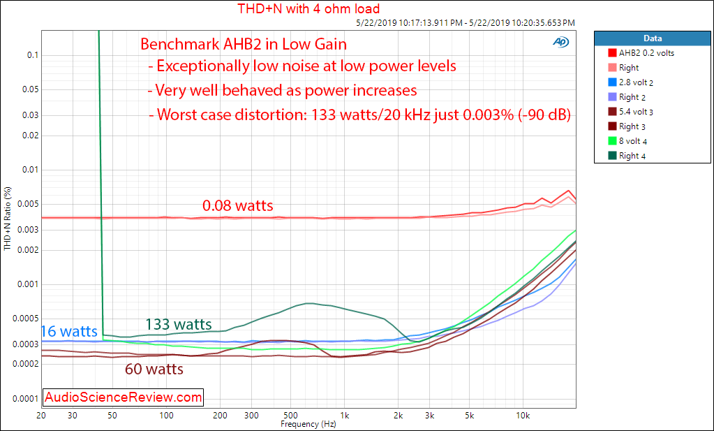
I show that in my THD+N versus frequency:I would like to see harmonic distortion measured at a frequency below mains frequency, say 40Hz here like HiFi News in the 1970s, to include power supply shortcomings, if any.
The almost vertical dark green lines on the left hand side, is that showing the amp cannot do high output at low frequencies?I show that in my THD+N versus frequency:
OP
- Thread Starter
- #454
It can't after a while. The protection circuits monitors conditions and makes a prediction after a while and shuts things down. I am not sure but I suspect if I started the sweep from left to right, it may pass it (current sweep is from right to left so the amp has been running at full power for a while).The almost vertical dark green lines on the left hand side, is that showing the amp cannot do high output at low frequencies?
Give us a call at 1-800-BNCHMRK and we will get this sorted out for you.Mine arrived mid-week and I installed them Friday night and Saturday morning. I have to contact support as 1) the speakers pop when the muting circuit engages and disengages and 2) the 12V trigger doesn’t work consistently. If I try it out repeatedly it’ll work, but both times I listened for over an hour it didn’t work on power off. The first time I had to turn all three amps off separetaly, and the second time the second amp turned of the third. Disappointing.
View attachment 27110
The protection circuits detect full amplitude sine waves and limit the amount of time these signals can be produced when driving a low impedance. The time limit is a function of output voltage and output current. @amirm may be able to tell us the total sweep time before shutdown. He is correct: If the sweep was from low frequency to high frequency, the protection would have activated on the high-frequency side of the graph. A faster sweep time would allow a complete sweep before triggering the protection. Music cannot activate this protection mode. It just protects the amplifier from test bench abuse.It can't after a while. The protection circuits monitors conditions and makes a prediction after a while and shuts things down. I am not sure but I suspect if I started the sweep from left to right, it may pass it (current sweep is from right to left so the amp has been running at full power for a while).
digitalfrost
Major Contributor
Well, after reading the review of the Nord NC500, this pushed me over the edge and I finally ordered the AHB2. I've been interested in this amplifier since a couple of years ago. With Eigentakt on the horizon, this still seems like the best option.
In any case, I gotta hear it for myself and I know I won't get a half assed product. I can certainly built the NC400 modules myself, but I have no respect for the shoddy engineering of some of the NC500 amplifiers. This doesn't only include boutique brands but also NAD with their M22 which shows much worse measurements than the DIY implementation.
In any case, I gotta hear it for myself and I know I won't get a half assed product. I can certainly built the NC400 modules myself, but I have no respect for the shoddy engineering of some of the NC500 amplifiers. This doesn't only include boutique brands but also NAD with their M22 which shows much worse measurements than the DIY implementation.
Last edited:
dkfan9
Member
As you have suggested, the frequency response variations are much too small to be significant. You would discover much larger variations between the left and right speakers and between speaker samples. You would also discover larger variations by moving you listening location by an inch or two. I would be more inclined to look at THD differences and phase response differences.
I will say that I like the numeric calculations that you have made to combine the speaker data with the amplifier data to predict the system frequency response - nice work!
Thanks! It was an issue on my mind for a while now so it was rewarding to put it all together.
I absolutely agree that the differences will be less than speaker variation (even within a pair as you note), and less important to fidelity than the THD and phase differences you mention. But as @Blumlein 88 said, given a set of speakers, I think these variations certainly could be audible when comparing amps, both related to the frequency response and the overall level differences, especially where the level differences are smaller than the volume control steps available prior to the amp. But as I hope I got across in the last graph, the small effect of the impedance interaction on fidelity to the source is not known without also looking at the speaker response.
I think the greater importance of distortion and noise performance vs small changes in FR becomes clear when you consider @JohnPM 's graph from his post earlier, showing the additional IMD generated in a chain with added HD.
And as @tktran303 pointed out earlier, a loudspeaker will usually produce more distortion from a given signal than any electronics in the signal chain--i.e. if you replaced the loopback with a speaker, that graph would look worse. I think it's a little more complicated than
At levels where transducer distortion will be high enough to mask amplifier distortion, the transducer will also be creating new non linear distortions based on any non linear distortions in the signal chain--in effect amplifying the problems in the amplifier (or other device). At levels where the transducer is introducing fewer distortions, any masking effect will be less significant. Unfortunately measuring this at the loudspeaker end is very difficult for most of us, due to microphone capability and environmental noise.So of course whatever problem in the amplifier is masked by the transducer.
This figure you give for the amplifier equivalent impedance--is this simply the real (resistive) part of the complex impedance? That's what it looks like based on punching those numbers into an impedance file and entering it into DATS, but i want to make sure I'm not missing anything.From the amplifiers perspective, -45 degrees at 4 Ohms is equivalent to driving a 2.8-Ohm resistive load. [...] -50 degrees at 4.1 Ohms is equivalent to driving a 2.6-Ohm resistive load.
For those whose eyes may have had a problem reading @dkfan9 highly relevant fine print.")
I mean, I know at least I'm over here living inside a dream...
4 ohms at -45 deg = 2.83 ohms - j2.83 ohms -- real and imaginary parts of the impedance, yes (j = sqrt(-1)).
A angB = A cosB + j*A*sinB = x + jy
A = sqrt(x^2 + y^2), B = arctan(y/x)
Edit: Corrected sign error in imaginary term; magnitude of numbers does not change. Flips phase from positive (inductive) to negative (capacitive).
A angB = A cosB + j*A*sinB = x + jy
A = sqrt(x^2 + y^2), B = arctan(y/x)
Edit: Corrected sign error in imaginary term; magnitude of numbers does not change. Flips phase from positive (inductive) to negative (capacitive).
Last edited:
dkfan9
Member
This is the most straightforward laying out of the equations I've found, given the magnitude and phase. Thank you!4 ohms at -45 deg = 2.83 ohms + j2.83 ohms -- real and imaginary parts of the impedance, yes (j = sqrt(-1)).
A angB = A cosB + j*A*sinB = x + jy
A = sqrt(x^2 + y^2), B = arctan(y/x)
Similar threads
- Poll
- Replies
- 543
- Views
- 81K
- Poll
- Replies
- 146
- Views
- 24K
- Replies
- 57
- Views
- 11K
- Replies
- 1K
- Views
- 174K