• WANTED: Happy members who like to discuss audio and other topics related to our interest. Desire to learn and share knowledge of science required. There are many reviews of audio hardware and expert members to help answer your questions. Click here to have your audio equipment measured for free!

O-Noorus D1 - TPA3255 PFFB Stereo Amplifier - Front Display, Tone Control (with bypass) and Remote

People hi !

@ dr_mick51: You got it all figured out ;)

The 220pF capacitors are a modification identical to the one proposed by Lester (SYLPH AUDIO) on its PCB in order to correct the appearance of the frequency response for the extreme treble which have a very slight rise ->

View attachment 406201
??
That graph shows SYLPH-D200 frequency response with 4 and 8 ohm load, like in every amp review, not before/after any mod. Original here:

1731837102374.png


and the result shown is very different and much better to that shown by @FanatNsk , who has +0.5 dB at 20kHz while SYLPH has much less.


and by the way, the data you find in the datasheet of the chip is at 75°C not because they measure 75°C on the chip, but because the set on purpose the temperature of the heat sink to 75°C when they do the measurements, they chip itself is surely hotter than that. from the datasheet pag 32:

1731837796289.png
 
Last edited:
ICIETDIYEUR

In my opinion, the parameters of the power supply are of great importance for amplifiers.
Especially the value of the output resistance and its dependence on frequency.
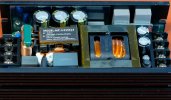
The SMPS of Topping amplifiers are very good.The sound of D1 with SMPS PA5 is almost the same as with a transformer power supply.

Good SMPS is sold on the Ali website.
 

Attachments

  • SMPS.jpg
    SMPS.jpg
    206.1 KB · Views: 51
Last edited:
@ MCH

My SYLPH audio graph is an illustrative image as surely everyone has understood but if I have explained myself badly then here it is: the goal of this "mod" is to attenuate this rise in the treble.

Now you cite FanatNsk's measurements but you forgot to read that I tell him that his modification is incomplete but above all incorrect (look at my post on this point) so the measurements made give results that are distorted.

Concerning temperatures, I think that all readers know how to read, interpret this part of the datasheet and will have been able to draw the "lessons" that result from it.

However, I don't necessarily agree with you (although they use a "normalized" heatsink) because the term "Tc" is mentioned in which "c" normally means "case"...

However, on a DIY amp that I made with a two-chip PCB TPA3255 in PBTL mode powered by 52V/11.5A, I actually measure 75°C in the center of each heatsink.

@ UAN
It will be said that you are probably right since it is your opinion that is only your opinion.

The photo of an SMPS that you show taken from ALIEXPRESS only exists in 24V max. not enough in my opinion.

Now to be sure of what you are saying, you would have to have the measurements of each of his power supplies to compare them: I don't have them.

However, I note that you did not talk again about the cost price of a linear power supply compared to an SMPS....
... But anyway, will you hear the difference you're going to get from the measurements when listening ?

Perhaps we are also in the presence of an "inverted psychoacoustic phenomenon" on this point ?

Indeed, it is not because we do not measure (or we do not know) to measure a "sound effect" (perception/subjective) that it does not exist and conversely it is not because we measure an effect (because we know/objective) that it is necessarily audible.
 
ICIETDIYEUROf,
course, this is my subjective opinion, not confirmed by measurements.
The result of long-term listening.Photo SMPS 24 V this is my photo, but from another amplifier.
These SMPS are easy to find on the Ali website, they are also available for 48 +-5 V, 5 A. I recommend buying, it is very high quality.

Now I have a linear transformer power supply installed.I am a radio amateur with a lot of experience and I have a lot of parts, including transformers on a torus.If the mail to France worked,I would give you a good network transformer.
 
@ UAN

I have absolutely no doubt about your abilities and knowledge, and even less about your sympathy :cool:

Your proposal is much more than that, even if it will not see the light of day because of mail problems, but I still thank you for your gratitude :)

However, regarding the power supply you present: it is not that good (see ripple) but above all it does not correspond to my needs :(

Here is the supplier's documentation ->

PSU.jpg


As I often write: it's not me who says it but the designer ;)
 
Last edited:
  • Like
Reactions: UAN
Clarifications for forum readers.

As UAN pointed out: a linear power supply will give much better results than a switching power supply but it will have a much higher cost of production :mad:

To illustrate my words, here is an example of a linear power supply that I use for my DAC:

I chose it for its qualities but especially for its price, which remains affordable since its power is much lower than for the needs of an amplifier (15VA for my DAC while for a class D amplifier like O-NOORUS D1 it will be around 250 to 480VA usually met depending on the needs).

1.jpg

2.jpg

3.jpg

4.jpg

5.jpg

6.jpg


Materials used for this PSU:

- TALEMA 15VA ultra-low noise transformer commonly used by major audiophile brands
- Thick, textured aluminum alloy shell with heat dissipation to ensure heat dissipation
- Copper DC Output Block Made in Taiwan
- LT1085 Low "Stall Voltage" Regulator
- Taiwan-made power outlet with Tyco "self-recovery" switch to improve electrical safety
- Integrated PCB design with no internal wiring
- "Silver" soldering done "by hand"
- NIPPON CHEMI-CON KY Electrolytic Capacitors
- VISHAY Diode High Current Rectifier Bridge

Conclusion:

As we can see, there is no equivocation regarding the quality of a linear power supply (as long as it is well made with good materials like the one presented here) compared to a switching power supply of any kind since we can never obtain such a low ripple (to my knowledge).
 
As we can see, there is no equivocation regarding the quality of a linear power supply (as long as it is well made with good materials like the one presented here) compared to a switching power supply of any kind since we can never obtain such a low ripple (to my knowledge).
https://linearaudio.net/silentswitcher although you could argue it's a hybrid - switching doing the bulk of the work, with linear cleaning it up without having to waste too much power. Neurochrome has similarly used off the shelf SMPS followed by LC filter to take out the HF, allowing use of cheaper linear regs that don't have the HF performance of those in the Silent Switcher. Not that you always need this level of performance given the improvements in PSRR (especially at HF) for some circuit designs.
 
Hi somebodyelse :)

This is a great example that I did not know about and I thank you for sharing ;)

Nevertheless, not to stray from the subject discussed in this post (the O-NOORUS D1 amplifier):
I doubt that this type of power supply can have a model with a power capable of powering a class D amplifier and if this were the case, once again, it would be overpriced compared to a switching power supply "traditionally" used with this type of amplifier and of course more expensive than the amplifier itself :mad:

Indeed, we are talking here about a "mainstream" amplifier, accessible to all in terms of price positioning and not a "high-end" device and this is the reason why I simply proposed a simple, effective and low-cost "MOD", if you don't use a WIMA MKS2 of 10μF/50V it is true, knowing that you can in this case keep the original ones which do not affect the main interest of the "MOD":

- Rebalancing of the signals at the input of the chip TPA3255
- Attenuation of the rise in the treble at very high frequencies

PS: otherwise you can always use batteries but you will have to think about recharging them :D
 
Last edited:
Hi @somebodyelse :)

Here is my thought regarding the power supply needed for a TPA 3255-based amplifier or PCB:

As a "general rule" these designs are rather located between the low end and the mid-range depending on the models found in the trade (rarely high-end), so they will be offered at an affordable price, so it would be necessary for their power supply while ensuring an operation that allows to "get the maximum" from the capabilities of the TEXAS INSTRUMENTS TPA3255 chip.

As an introduction, here is an old post from the TI forum ->

TPA3255 recommanded supply.jpg

Here are some power supplies that may well meet the previously announced criteria:

1> 600W LLC Power Supply (about 30$)
1PSU.jpg


2> 600W LLC Power Supply with PFC (about 50$)

2 PSU.jpg


3>
400W LLC Power Supply with PFC (about 35$)

3 PSU.jpg

This last power supply has "only" 400W but will be more than enough for the different needs.

It should be noted that the model proposed in 48V/8.3A also meets the "criteria" that AMIRM had set out in these recommendations regarding the PSUs necessary for a good use of the TPA3255 chip :cool:

Finally, you will notice that I have not given a link to the models presented here but you can easily find them with, for example, the product search function by its photo available on the AliExpress resale site ;)

PS: I just wanted to specify that I myself have used these 3 PSU models with DIY creations or commercial amplifiers without encountering the slightest problem of operation or heating.
 
People hi !

@ dr_mick51: You got it all figured out ;)

The 220pF capacitors are a modification identical to the one proposed by Lester (SYLPH AUDIO) on its PCB in order to correct the appearance of the frequency response for the extreme treble which have a very slight rise ->

View attachment 406201

If soldering the legs of the FKP2 220pF is a problem for you in this area then you can use SMD components otherwise the other solution is to solder the FKP2 directly on the pins of the OPAMPS located below the PCB, it is much more convenient. Regarding the original input resistor, it's a 22K (it's easier for me to say because I have the O-NOORUS original diagrams :cool: ). It must be replaced by a 220K for obvious reasons of adaptability of the output impedance of the device that will be connected to it.

I will try to explain: the NJW-1194 volume control has an input impedance of 15 to 20 k, which is probably variable depending on the level setting, and which comes in parallel with this 22 k R... So it's in your best interest to increase this R, you can go up to 220 kO.

Reminder:
In electronics (not limited to audio), any active system has a resistance (input, output, etc.) that is never linear but varies +/- depending on the frequency of the signal. We therefore use the notion of impedance to differentiate from pure resistance. To come back to the pairing of devices. In the case of HiFi, the ideal is for the output impedance of a device to be very small compared to the input impedance of the device to which it sends its signal. The smaller the output impedance, the more current the device can "send", and therefore not be disturbed "too much" by its load (the load, here, is the device to which it is connected). Conversely, the smaller the input impedance of a device, the more current it will "consume", and potentially disturb the source device.
If output = low impedance --> not easily disturbed If input = high impedance --> doesn't disturb much We quickly understand that the 2 together is even better! On the contrary, if the output impedance is high and the input impedance is low, very large signal disturbance in perspective (attenuation, distortion,....) If the impedances are more or less equal, we will experience a good attenuation (math shows that if the impedances are equal, the amplitude of the signal is divided by 2 exactly), and we also run the risk of disturbance (distortion).

Here is an explanation by an image of the PCB for a better understanding of the MOD ->

View attachment 406181

In this photo, the amplifier's gain is increased to 27.6dB with the 24K resistors. On my diagram (with the resistors of 15K instead of 24K) the amplifier's gain is 23.5dB.

As you have understood: the changes are in orange. The two capacitors are removed because they are absolutely useless since link capacitors are already present upstream of the TPA3255 and concerning the NJW194, nothing is indicated in the datasheet. It is good to remember that the use of bipolar type operational amplifiers is not recommended with this diagram since the resistance to the inputs will have a high impedance and its impedances will not be equal elsewhere, which will cause OFFSET! So, we will use FET or JFET type operational amplifiers because they are almost insensitive to this imbalance and are adapted to high impedances (it's not me who says it but TI). References such as OPA1656 or OPA1642 are well suited for this tour. I chose the OPA1642 not because of the measurements but for their "subjective" sound rendering...

... I find that the OPA1656 created a kind of "spacialization" effect on certain tracks or channels, which is not the case with the OPA1642 which seemed more natural to me and also has a softer extreme treble that will avoid possible "phenomena" of sibilance. This cannot be measured, it is a personal feeling (which my friends also share), however these two references will have very good results that are also very close to the measurements if we want to remain objective :)


@ FanatNsk::
You absolutely have to put the 4 capacitors of 220pF because as it is, you create an imbalance of the signals that are expected as "symmetrical" by the TPA3255 chip.

PS: I take advantage of this post to talk about the "heating problems" with the D1: there is none! This feeling is felt by the fact that the material (and its thickness) of the case used is different from those of the competition (FOSI., AIYIMA,...). I invite readers to read TI's datasheet about the TPA3255 amplifier chip and to look carefully at the temperatures measured for a given voltage: on the tables it is indicated 75°C for a voltage of 51V and the Tjmax.de the chip is 125°C. So with the 42°C that I read with the laser thermometer in the center of the top of the case of my D1 powered by 42V/8.3A, I am in completely normal conditions of use even if the feeling of heat is slightly greater than with other amplifiers on the market. Another explanation comes from the use of PFFB which leads to a higher heating rate unlike amplifiers which are not equipped with it.

NOTE: my sytem with 8 Ohms speakers -> (42 VDC x 0.707)^2 / 8 Ohms = 110 Watts

View attachment 406198

For example, to "counteract" this feeling effect, AIYIMA on its A70 model which has the PFFB used a large aluminum "cube" as a contact sink in its case. However, the TPA3255 chip still works under the same conditions as the O-NOORUS D1 amplifier ->

View attachment 406279

It's a bit like I gave you a pair of insulated gloves with the amp to reassure you (LOL).

In addition, the advertisement for the A70 model is false because even with a 48V 10A Gan power supply, the 300W advertised is not reached with 4 Ohm speakers ->

(48 VDC x 0.707)^2 / 4 Ohms = 287.91 Watts.

It's not me who says it but the mathematical formulas :rolleyes:

Have a good day and happy listening to all.
Hi, I'm confused with the resistor values. The schematics values don't match the values shown on the pcb. My understanding is, if you want to apply any type of gain(increase or decrease the input signal) that would be in the first opamp stage (Left of each opamp). The second stage(which is fed from the output of first stage) is an inverting stage with unity gain. This means both resistors need to be of identical values on that second stage (Right of each opamp). If one resistor is bigger or smaller than the other (as you are sh8w8ng 10k and 15k) then you won't have unity gain anymore, and both legs(left or right) won't have the same gain: positive swing will be higher than the negative swing, and therefore you are feeding a distorted differential input signal.
Can you please confirm? I understand you want to "increase" the amplifier gain by increasing the input resistor, but I think you are actually decreasing the gain. On an inverting opamp( like in this case) the feedback resistor need to be bigger than the input resistor to have a bigger output.
On the original schematics the input resistor is 10k, and the feedback resistor was 15k.
If you replace the 10kOhm with a 27kOhm you are reducing the output(According to what the picture shows). But then you say:
Screenshot_20241124_102127_Chrome.jpg

So, you are saying you replaced the 15k with a 24k, so the picture should show a 24 or 27k input resistor and a 10k feedback resistor.
But the image shows 24k and 15k , not 10k
D1 MOD.jpg

Also, it is my understanding of the circuit that the bottom resistor is the input resistor(you can see how it comes from the bottom coupling capacitor), and the middle one is the feedback resistor. The top resistor is the output resistor.
So, I think you are showing/replacing the wrong one.
Screenshot_20241124_101203_Chrome.jpg

Screenshot_20241124_104342_Chrome.jpg

And I have another question. Why one would like to increase the gain?. I see that the best performing amplifiers have a low gain. Does not it make more sense to reduce the gain?. By increasing the input resistor value as shown on your picture?.
But again , what I cannot fully understand is why the resistors on the second stage have different values, when they are suposed to be the same value to keep unity gain and only inverting the signal one last time.
I'm really interested in this mod. Those Melf resistors are size 0204 right? Can you recommend ones?. I see several options in digikey.com
 
Good evening.

I don't want to "scatter myself" in endless explanations so here is in detail what was done on my amplifier in the hope that it brings enough answers to your questions ->
NOTE: for information, the gain here is the same as that of Lester's PCB in the "SE" version (Sylph Audio)

1 - D1 MOD.jpg


2 - Diagram.jpg

Explanations ->

3 - .jpg


4 - Explainations.jpg


NOTE: the NJW-1194 volume control has an input impedance of 15 to 20 kO, which is probably variable depending on the level setting, and which comes in parallel with the 10 kB resistor at the entry... So it's in your best interest to increase this resistor, you can go up to 100 kO or even 220 kO...

In electronics (not limited to audio), any active system has a resistance (input, output, etc.) that is never linear but varies +/- depending on the frequency of the signal.
We therefore use the notion of impedance to differentiate from pure resistance.

To come back to the pairing of devices:

In the case of HiFi, the ideal is for the output impedance of a device to be very small compared to the input impedance of the device to which it sends its signal.

The smaller the output impedance, the more current the device can "send", and therefore not be disturbed "too much" by its load (the load, here, is the device to which it is connected).

Conversely, the smaller the input impedance of a device, the more current it will "consume", and potentially disturb the source device. If output = low impedance --> not easily disturbed If input = high impedance --> doesn't disturb much.

We quickly understand that the 2 together is even better !

On the contrary, if the output impedance is high and the input impedance is low, very large signal disturbance in perspective (attenuation, distortion,....)

If the impedances are more or less equal, we will experience a good attenuation (math shows that if the impedances are equal, the amplitude of the signal is divided by 2 exactly), and we also run the risk of disturbance (distortion).

That's about IT.

Now, you're telling me that the values indicated on the diagram are not the ones on the amplifier ?
I suggest you measure them again or we don't have the same O-NOORUS D1 amp (of which I have the original diagram as well as those of the other models but also those to come, including 2 models very soon... but I didn't say anything) which has not undergone any modification unless there was to be a second version but this is not yet the case... For now.

Also you write that the best class D amps have a lower gain ?
Which ones, do you know it ? (FOSI, AIYIMA, TOPPING,....)
Can you tell me the gain of a PURIFI amp for example ?
Does it have a lower gain ?
I don't think Bruno (PUTZEYS) conceived it that way...
...and it seems to me that its direction is not too bad (LOL).

As far as resistance is concerned, the main thing is to take it with the right values: taking "GOLD" models, big brands or with high prices will have a much greater influence on the state of your finances than on the measurements.

Regards.
 
Last edited:
Good evening.

I don't want to "scatter myself" in endless explanations so here is in detail what was done on my amplifier in the hope that it brings enough answers to your questions ->
NOTE: for information, the gain here is the same as that of Lester's PCB in the "SE" version (Sylph Audio)

View attachment 409277

View attachment 409278
Explanations ->

View attachment 409279

View attachment 409280

NOTE: the NJW-1194 volume control has an input impedance of 15 to 20 kO, which is probably variable depending on the level setting, and which comes in parallel with the 10 kB resistor at the entry... So it's in your best interest to increase this resistor, you can go up to 100 kO or even 220 kO...

In electronics (not limited to audio), any active system has a resistance (input, output, etc.) that is never linear but varies +/- depending on the frequency of the signal.
We therefore use the notion of impedance to differentiate from pure resistance.

To come back to the pairing of devices:

In the case of HiFi, the ideal is for the output impedance of a device to be very small compared to the input impedance of the device to which it sends its signal.

The smaller the output impedance, the more current the device can "send", and therefore not be disturbed "too much" by its load (the load, here, is the device to which it is connected).

Conversely, the smaller the input impedance of a device, the more current it will "consume", and potentially disturb the source device. If output = low impedance --> not easily disturbed If input = high impedance --> doesn't disturb much.

We quickly understand that the 2 together is even better !

On the contrary, if the output impedance is high and the input impedance is low, very large signal disturbance in perspective (attenuation, distortion,....)

If the impedances are more or less equal, we will experience a good attenuation (math shows that if the impedances are equal, the amplitude of the signal is divided by 2 exactly), and we also run the risk of disturbance (distortion).

That's about IT.

Now, you're telling me that the values indicated on the diagram are not the ones on the amplifier ?
I suggest you measure them again or we don't have the same O-NOORUS D1 amp (of which I have the original diagram as well as those of the other models but also those to come, including 2 models very soon... but I didn't say anything) which has not undergone any modification unless there was to be a second version but this is not yet the case... For now.

Also you write that the best class D amps have a lower gain ?
Which ones, do you know it ? (FOSI, AIYIMA, TOPPING,....)
Can you tell me the gain of a PURIFI amp for example ?
Does it have a lower gain ?
I don't think Bruno (PUTZEYS) conceived it that way...
...and it seems to me that its direction is not too bad (LOL).

As far as resistance is concerned, the main thing is to take it with the right values: taking "GOLD" models, big brands or with high prices will have a much greater influence on the state of your finances than on the measurements.

Regards.
Good evening. This is a picture of my amp
20241124_145031.jpg

As you can see it has 10k and 15k on both input and feedback resistor for both opamp stages on each opamp.
It is my understanding that the first opamp stage(left side of each opamp) is used for the unity gain inversion and you can see it is fed from the output(pin 7) of the 2nd stage (right side of each opamp) via the left eletrolytic capacitor on each opamp.
Also this is the cause of my confusion because this is the resistor(bottom left from each opamp) you recommend to replace for 24k originally.
Based on the schematics and the pcb traces the resistor you should replace is the bottom right one to be able to change the gain on the input stage (right side of each opamp).
The first picture you posted showed a 24k resistor on that bottom left resistor (this is the stage that is used for the unity gain inversion):
D1 MOD (1).jpg

Then you posted a similar but different picture, now with a 15k resistor to correctly match the other resistor above it which is 15k also:
1 - D1 MOD.jpg

Now, from my picture you can see that the resistor on that position is a 10k resistor instead of the correct value 15k. You did not show a picture of the original resistor value on that position. Did you also have a 10k resistor there like mine and hence the whole reason of the mod?, which is more like a fix to me. Or you had a 15k resistor there?
I think it is clear for me that I need to replace that resistor.
I already did the 220p capacitor. I soldered directly to the opamp socket pins on the back of pcb. And I also solder a shunt for all the 4 bottom 10uF. The amp sounds better right away. But I cannot stop thinking about that bottom left resistor(10k instead of 15k).
@FanatNsk can you confirm what resistor value you have/had on the position(bottom left on each opamp)
 
Good evening.

Here is the picture of my PCB before the modifications ->

Original design.jpg


As you can see on the 'MOD' image, it's the 10K resistor at the bottom left of each OPAMP that needs to be replaced by a 15K one, like on my O-NOORUS D1 model.

As mentioned in a previous post, the 'MOD' thus made reflects the schematic of the Sylph Audio PCB for which I had had many exchanges with Lester (The manager/designer of Sylph Audio)...

The same is true for O-NOORUS (Mr YIN, director and designer) with whom I exchange EVERY DAY on his creations/designs and necessarily on the diagrams of his existing and future achievements (very soon :D ).

I have ALL the original diagrams and I know them perfectly since this has been mainly the subject of our discussions ;).

That says it all :)

I take advantage of this post to direct you to an interesting discussion with Bruno Putzeys :cool: (Mola-Mola, Hypex, and Grimm Audio,....) where many interesting topics and information are mentioned in the discussion -> here

Regards.

PS: I tested "a whole lot" of OPAMPs with this amplifier like NE5532 (originally mounted), TL072, OPA1612, OPA2211, OPA1642, OPA1656, OPA2156, OPA2828,... and the only one that gave me the best feeling was the OPA1642.

This is of course a 'subjective' notion from a certain point of view, although we could draw some "lessons" or reflections from Bruno Putzeys if we refer to the article contained in this post, so it is simply advisable to try various models to form one's own opinion.

However, I insist once again that in theory, BIPOLAR amplifiers are not suitable for the scheme of this amplifier for which the input impedances "seen" by the OPAMPs are not balanced but also far too high.
 
Hello.

A few small, less 'subjective' examples about OPAMPS ->

1> the diagram of O-NOORUS D1

2 - Schéma Jesse - Corrigé envoyé à Francis pour explication.jpg


2> general behaviour of OAMPS according to their type (bipolar or FET)

XXX - Comparison BIPOLAR-FET.jpg


We immediately note that according to this TI table, bipolar OPAMPS should not be retained


A little explanation:

we expect a so-called 'Hi-Fi' device to cover the frequency band between 20 and 20000 Hz in the 'best' way, in other words, with as little distortion as possible, right?

A simple calculation will allow us to obtain a 'performance indicator' ->

bandwidth to be covered from 20 to 20000 Hz or 19980Hz.

Then we set √Hz = 141.35
then the DATASHEET of the OPAMP concerned, knowing that the value that will be given to us is for a precise resistance quantity (the value that we read increases with the resistance as seen in the previous table).

To calculate the input voltage noise that I will obtain, I take for example a value of 5nV/√Hz read in the datasheets of the OPAMP that I want to use.

I then perform the following calculation -> 5nV/√Hz x 141.35 = 706.75nV

I just got the input voltage noise from my circuit for the selected OPAMP.

We proceed exactly the same way for input current noise, knowing that it is about 1000 times lower with a FET type OPAMP.

Here we have obtained a first non-negligible and very 'objective' indicator ;)

Now let's move on to a second table for which I don't need to make comments with known OPAMPS ->

GOOD to KNOW.jpg


I hope this will allow you to see a little more clearly than your ears which are made to hear :D

Regards.
 
and the result shown is very different and much better to that shown by @FanatNsk , who has +0.5 dB at 20kHz while SYLPH has much less.
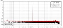
Here is a graph of the measurement with a 4 Ohm load.
Spectrum.png
 
Hello.

A few small, less 'subjective' examples about OPAMPS ->

1> the diagram of O-NOORUS D1

View attachment 410085


2> general behaviour of OAMPS according to their type (bipolar or FET)

View attachment 410086


We immediately note that according to this TI table, bipolar OPAMPS should not be retained

A little explanation:

we expect a so-called 'Hi-Fi' device to cover the frequency band between 20 and 20000 Hz in the 'best' way, in other words, with as little distortion as possible, right?

A simple calculation will allow us to obtain a 'performance indicator' ->

bandwidth to be covered from 20 to 20000 Hz or 19980Hz.

Then we set √Hz = 141.35
then the DATASHEET of the OPAMP concerned, knowing that the value that will be given to us is for a precise resistance quantity (the value that we read increases with the resistance as seen in the previous table).

To calculate the input voltage noise that I will obtain, I take for example a value of 5nV/√Hz read in the datasheets of the OPAMP that I want to use.

I then perform the following calculation -> 5nV/√Hz x 141.35 = 706.75nV

I just got the input voltage noise from my circuit for the selected OPAMP.

We proceed exactly the same way for input current noise, knowing that it is about 1000 times lower with a FET type OPAMP.

Here we have obtained a first non-negligible and very 'objective' indicator ;)

Now let's move on to a second table for which I don't need to make comments with known OPAMPS ->

View attachment 410093

I hope this will allow you to see a little more clearly than your ears which are made to hear :D

Regards.
Thank you, that was very informative but a little hard to digest.
I only have one observation: On the last graph you picked 10k and 50k, not 15k. 15k is between the 10k and the next 20k line. But your conclusion still apply. Thanks. I'll try those opamps
 
This is my measure 4Om 3W (3.5Vrms out) after update D1 (replacing resistors and put 220pF capacitor in hole place around operational amplifier)
View attachment 405392
View attachment 405394
View attachment 405395
This for 8Om 6.3W (6.5Vrms out)
View attachment 405396
View attachment 405397
View attachment 405398
View attachment 405399
I installed it according to this scheme, only 2 single capacitors, I didn’t install those that are in pairs.


View attachment 405400

I chose 27kOhm resistors, the heating at idle became a little less.
View attachment 405401
Nice, so basically you fixed the extra gain on the inverting stage by replacing the 10k resistors from the bottom left on each opamp, and also increased the overal gain on the first stage by increasing from 15k to 24k or 27k.
And you just reused those 15k resistors you removed and solder them into the other stage.
Can you retest but now with all 4x 220p capacitors? It is my understanding that you only installed 2, right?
 
Hi all :)

dr-mick51 you have a relevant eye ;)

I apologize to the readers for making this mistake :oops:

I was indeed too enthusiastic to communicate this information to you, which produced this inattention on my part and I am very sorry :(

Here is the correction ->

AOP.jpg


Best regards.

PS: NJM071 is comparable to TL071 (TL072 in dual version).

NB: Dealers use in their assemblies the OPAMP NE5532 (largely outdated nowadays) which are of the bipolar type (therefore not suitable here but also on other class D amplifiers in general) ONLY for a question of cost price because their price is close to zero !
Indeed, as seen above, they create an OFFSET at the input of the circuit (and therefore noise) which forces the use in series of chemical capacitors called "link" (not suitable for the signal path either) which will "dirty" the signal without having totally "disappeared" this OFFSET...... if at least to be effective, these capacitors could be of the "film" type but this is not the case :facepalm:

Explanation about chemical capacitors:
A chemical capacitor needs at least 2 to 3 V between its terminals to simply "exist"!
Below this voltage, the electrolyte does not work (it is not ionized and does not conduct) and the condo does not transmit the signal properly :(

You will now understand a little better some details of my 'MOD' :)
 
Last edited:
Hi.
I replaced the op-amp in D1 with LM4562 and the sound became much better. I could not find information on the network about the input type of this op-amp - bipolar or MOS. Judging by the value of the input current, it is MOS.
The harmonic level did not change, the same with both 5532 and LM4562.
 

Attachments

  • Noorus D1-  (BP).jpg
    Noorus D1- (BP).jpg
    108.2 KB · Views: 19
Back
Top Bottom