Before I get into the weeds of it, I would just like to say that this place is much more invested in the scientific aspect of audio as opposed to the "flavor" of it so thank you for existing because all of these DIY audio forums are deteriorating what little sanity I have left by giving too many opinions as opposed to raw data.
Moving on! (oh and warning: INCOMING WALL OF TEXT)
So I'm building a set of speakers. I was lucky enough to find a good deal on KEF SP1632s so I decided to pull the trigger on a new project. I'm pairing them with the Dayton E150HE-44 so I can have a compact 3-way speaker with good overall frequency response. While trying to design the crossover I came across something called zobel networks, and the lattice phase equalizer. I thought it would be a neat idea since these filters are good for not just splitting frequencies, but maintaining the phase relationship of a balanced line. So I did a rough draft of the design, did some math, downloaded VituixCAD, and tried putting together a prototype.
It was shit. Complete and utter shit.
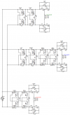
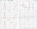
When I finished prototyping the circuit in CAD, the frequency response curves looked NOTHING like the LR4 network I had in mind. That being said, if someone would be so kind as to give my circuit a once over I would be most appreciative. I'll post links to all the material I used in order to get the numbers I have in the schematic, as well as said schematic and the info the CAD is spitting back at me.
Crossover calcs (https://www.diyaudioandvideo.com/Calculator/ApcSpeakerCrossover/)
Zobel/Lattice info (https://en.wikipedia.org/wiki/Zobel_network) (https://en.wikipedia.org/wiki/Lattice_phase_equaliser) (https://physics.stackexchange.com/questions/301342/transfer-function-of-a-lattice-phase-equalizer) (https://audiojudgement.com/impedance-equalization-circuit-zobel-network/)
Sub specs and CAD info (https://daytonaudio.com/product/191...-mmag-extended-range-subwoofer-4-ohm-per-coil)
Mid/Tweeted specs and CAD info (https://www.audioexcite.com/?page_id=3614) (https://www.diyaudio.com/community/threads/small-3-way-with-kef-sp1632-sb-acoustics.233572/page-2) (https://us.kef.com/products/r3)
While I'm here, I figure I would also ask about the part selection as well. Since I'm only going to be going for about 50-100 watts handling, could I use high power RF on-board components as opposed to the large chunky passives ordinarily used in audio circuits? I figured A) since I'm not going overboard on power and RF chips usually can handle a few amps why not? B) It would give me an opportunity to use precision components as opposed to the +/- 3-5% on typical audio components, and C) Despite them having much higher specs, they're still cheaper than Mundorfs lol
Looking forward to the responses and thanks for the help!
Moving on! (oh and warning: INCOMING WALL OF TEXT)
So I'm building a set of speakers. I was lucky enough to find a good deal on KEF SP1632s so I decided to pull the trigger on a new project. I'm pairing them with the Dayton E150HE-44 so I can have a compact 3-way speaker with good overall frequency response. While trying to design the crossover I came across something called zobel networks, and the lattice phase equalizer. I thought it would be a neat idea since these filters are good for not just splitting frequencies, but maintaining the phase relationship of a balanced line. So I did a rough draft of the design, did some math, downloaded VituixCAD, and tried putting together a prototype.
It was shit. Complete and utter shit.
When I finished prototyping the circuit in CAD, the frequency response curves looked NOTHING like the LR4 network I had in mind. That being said, if someone would be so kind as to give my circuit a once over I would be most appreciative. I'll post links to all the material I used in order to get the numbers I have in the schematic, as well as said schematic and the info the CAD is spitting back at me.
Crossover calcs (https://www.diyaudioandvideo.com/Calculator/ApcSpeakerCrossover/)
Zobel/Lattice info (https://en.wikipedia.org/wiki/Zobel_network) (https://en.wikipedia.org/wiki/Lattice_phase_equaliser) (https://physics.stackexchange.com/questions/301342/transfer-function-of-a-lattice-phase-equalizer) (https://audiojudgement.com/impedance-equalization-circuit-zobel-network/)
Sub specs and CAD info (https://daytonaudio.com/product/191...-mmag-extended-range-subwoofer-4-ohm-per-coil)
Mid/Tweeted specs and CAD info (https://www.audioexcite.com/?page_id=3614) (https://www.diyaudio.com/community/threads/small-3-way-with-kef-sp1632-sb-acoustics.233572/page-2) (https://us.kef.com/products/r3)
While I'm here, I figure I would also ask about the part selection as well. Since I'm only going to be going for about 50-100 watts handling, could I use high power RF on-board components as opposed to the large chunky passives ordinarily used in audio circuits? I figured A) since I'm not going overboard on power and RF chips usually can handle a few amps why not? B) It would give me an opportunity to use precision components as opposed to the +/- 3-5% on typical audio components, and C) Despite them having much higher specs, they're still cheaper than Mundorfs lol
Looking forward to the responses and thanks for the help!