
SmellyCroc
New Member
- Joined
- Sep 29, 2023
- Messages
- 3
- Likes
- 2
Hi,
I'm diving into the world of DIY speakers and would appreciate some guidance regarding crossover components.
I've worked with electronic components in the past (industrial level) and am comfortable with the how and why, but audio seems a minefield of snake oil and profligacy, and I find myself a bit lost! I did swing by another diy forum but, despite some helpful folks, it felt quite cliquey and I'm not convinced I would have received the objective advice I'm after.
So, what manufacturers and specs should I be looking at if I want decent price/quality/performance? I'm in the UK, so local supply preferred, but it's not the end of the world if I must ship.
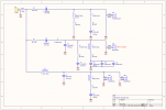
It's a long-term project (getting drivers is priority and currently have the woofers and mids) and the design is open source: SB Aacoustics Sasandu TX (The CX schematic is attached)
Thank you,.
SC
I'm diving into the world of DIY speakers and would appreciate some guidance regarding crossover components.
I've worked with electronic components in the past (industrial level) and am comfortable with the how and why, but audio seems a minefield of snake oil and profligacy, and I find myself a bit lost! I did swing by another diy forum but, despite some helpful folks, it felt quite cliquey and I'm not convinced I would have received the objective advice I'm after.
So, what manufacturers and specs should I be looking at if I want decent price/quality/performance? I'm in the UK, so local supply preferred, but it's not the end of the world if I must ship.
It's a long-term project (getting drivers is priority and currently have the woofers and mids) and the design is open source: SB Aacoustics Sasandu TX (The CX schematic is attached)
Thank you,.
SC
")
