• WANTED: Happy members who like to discuss audio and other topics related to our interest. Desire to learn and share knowledge of science required. There are many reviews of audio hardware and expert members to help answer your questions. Click here to have your audio equipment measured for free!

Is it possible to automatically correct the phase using REW arithmetics?

ernestcarl

Major Contributor
Joined
Sep 4, 2019
Messages
3,113
Likes
2,330
Location
Canada
Are you talking about this part?

View attachment 314151

If not, I want to ask if anyone knows why the line is not straight? I've never noticed this before on an unmodified graph. Usually, before the impulse begins, this line is strictly straight.


I've have made multi-point measurement, but I don't know if it suitable or not. Anyway I'll try to use it.

Yes. Likely when you introduced the subwoofer... I thought your speakers simply extended that low.

It's not a big deal.

If you average the multi-point measurements you should get less comb filtering. You should pay more attention to the RMS averaged response (no phase) when equalizing the magnitude response. And you can use the vector average while correcting the phase... but if the measurement distances are far apart, I would weigh the correction more heavily on the center MLP -- differences are not huge with your set of measurements, though.

*BTW, there's also RMS+phase avg which you can use. However, I notice that it produces some unwanted noise as well, so I might not use its phase information when performing trace arithmetic (extracted excess phase) and instead rely on the vector average.
 
Last edited:
gnarly

Major Contributor
Joined
Jun 15, 2021
Messages
1,035
Likes
1,471
I will try to explain the maths (much as I can understand) behind the ripples seen with measurements that are not full range Nyquist (ie 0-24,000Hz for 48,000Hz sampling rate):

REW's uses a "refined" version of the measurement method called ESS (exponentially swept sine). While the exponentially swept sine signal formulated (in discrete terms) below is being played,

x(k)=sin(w1 x K / ln(w2/w1) x exp(k/K x ln(w2/w1)); k=0,....,K (w1,w2 angular frequencies)

the recorded signal is convolved with the time reversed and -6dB/octave damped (amplitude rolled off) version of that excitation signal. Then, linear impulse response is separated and most of the harmonic distortion is passed on to the non-causal part.

The sweep needs to begin and end in zero phase to minimize any ripples due to the boundary effects at the start and end points. To achieve this, there are two adjustments made:

1. Fix the start and end frequencies and end the sweep in exactly the Nyquist frequency (w2=PI),
2. Let the sweep span a "fixed" number of octaves (w1=PI/2^p) where p is the number of octaves

With these changes, the start and end phase becomes:

phase(0)=(PI x K) / (2^p x ln(2^p)), phase(K)=(PI x K) / (ln (2^p)

Choosing K = M x 2^(p+1) x ln (2^p) , where M is an integer ensures that both endpoints will have the correct phase. However, since K is discrete and integer, two different values are needed for it; one ideal according to the previous criterion, and one rounded to the nearest integer. Having two different K values causes a frquency stretch by a factor of Kideal / K which should also be compensated in the time inversed x(k). The error is typically in the order of 10^(-6):

fs 48,000
Kmax 480,000
p 10
Kideal 468,456.591
K 468,457
Kideal/K 0.999999126
Thank you for that explanation. I wish I could fully follow it, but most of the math minor i got in college is long forgotten.

In layman's terms, maybe you can help with one facet of phase i still don't get.
Pragmatically, I view phase as relative between frequencies. So I ask myself which end of the spectrum should I use as reference, and the Nyquist end seems to make sense, because it is where any deviations from phase = zero degrees and t=0, have the least effect describing the relative relationship further down the spectrum.
I'm trying for example to say 1 degree of phase at 22Khz has a time representation equivalent of only 0.0009 degrees of phase at 20Hz.
Whereas of 1 degree of phase at 20Hz has a time equivalent of 1100 degrees at 22kHz. (Hope that made sense, and I did the math right !)

Anyway, when I measure acoustic phase traces, i always try to get the top end of the spectrum to have the phase trace at zero degrees, via removing the appropriate constant delay that equals time-of-flight and any other fixed time delays.
Which has worked super well in tying multi-ways together, especially using linear phase xovers.

Now, finally to my question....sorry for taking so long.
It seems correct to set phase equals zero at Nyquist. And to me, it intuitively seems that that's all that would be needed to measure relative phase throughout the rest of spectrum downwards.
But it appears to me that the Fourier math, the Hilbert transform, whatever is is inplay, needs a starting reference that phase is zero at 0Hz DC as well.
That phase isn't actually getting measured, but is derived.....and calculations are vs both ends of the spectrum having phase at zero.
Is that true? Is that part of what you were trying to explain with the math?
 

OCA

Addicted to Fun and Learning
Forum Donor
Joined
Feb 2, 2020
Messages
679
Likes
499
Location
Germany
Time delay caused by a phase shift should be calculated for a range in the frequency band, not for a particular frequency. This short tutorial will help you fully understand the subject:


and there's part II:


As per your other question, highest frequencies arrive first so it's logical to accept Nyquist as time 0 but this will be fully manipulated by system delays, clocking differences, etc. during different measurements so basing t=0 to DC will be more consistent at least between different measurements if calculated correctly.
 

gnarly

Major Contributor
Joined
Jun 15, 2021
Messages
1,035
Likes
1,471
Time delay caused by a phase shift should be calculated for a range in the frequency band, not for a particular frequency. This short tutorial will help you fully understand the subject:


As per your other question, highest frequencies arrive first so it's logical to accept Nyquist as time 0 but this will be fully manipulated by system delays, clocking differences, etc. during different measurements so basing t=0 to DC will be more consistent at least between different measurements if calculated correctly.

Thx. The McCarthy vids are a bit like second nature to me....his book is getting well worn :) ,
(also have had 8 days of classroom and field training with Smaart).
(So I've no problem with translating phase to time at a given frequency. Which honestly, I think is a misleading practice and should be dumped.
A misleading example is the commonly accepted idea that group delay can be used as as substitute for fixed delay in developing xovers..
Frequency defendant delays, and non-frequency dependent delays are simply not substitutes imso. But alas I seriously digress,,,,sorry...)

Back to my question....
Just as I think phase at 0 at Nyquist is the best phase reference for the rest of the spectrum, I think that also sets the t=0 reference for the rest of the spectrum.
So any measurements I make of system components, mainly other driver sections below VHF building DIY speakers, or time/phase alignments subs to mains etc,
are always with reference to phase and time both being zero at Nyquist.

I can't see using t=0 at DC as reference other than maybe in signal processing math, or perhaps excellent electronics, because flat response to DC is such an impossibility....especially acoustically. Heck, our linear based FFT programs can't even measure low frequencies constant delays accurately/repeatedly .

Whereas, t=0 at Nyquist is rock solid repeatable, with flat mag possible all the way out.

It seems to be, the math that looks to generating phase curves that must reference phase at zero, pose a theoretical imposition that's not consistent with reality...
ie phase ever being zero at DC.

The whole genesis behind my pondering all this goes back to step oscillations prior to impulse peak like Audioboy circled in #23.
I've found in REW, that where the sweep generators' starting frequency is set, relative to where the speakers response begins, has a big influence in the shape and oscillations of a step response before impulse peak. I know step is an integral of impulse......I'm just wondering how valid it really is for very low frequency work.

Again, sorry for delving so deep .. you presented a more simplified math explanation than usually encountered....thx again.
 
  • Like
Reactions: OCA

OCA

Addicted to Fun and Learning
Forum Donor
Joined
Feb 2, 2020
Messages
679
Likes
499
Location
Germany
Thx. The McCarthy vids are a bit like second nature to me....his book is getting well worn :) ,
(also have had 8 days of classroom and field training with Smaart).
(So I've no problem with translating phase to time at a given frequency. Which honestly, I think is a misleading practice and should be dumped.
A misleading example is the commonly accepted idea that group delay can be used as as substitute for fixed delay in developing xovers..
Frequency defendant delays, and non-frequency dependent delays are simply not substitutes imso. But alas I seriously digress,,,,sorry...)

Back to my question....
Just as I think phase at 0 at Nyquist is the best phase reference for the rest of the spectrum, I think that also sets the t=0 reference for the rest of the spectrum.
So any measurements I make of system components, mainly other driver sections below VHF building DIY speakers, or time/phase alignments subs to mains etc,
are always with reference to phase and time both being zero at Nyquist.

I can't see using t=0 at DC as reference other than maybe in signal processing math, or perhaps excellent electronics, because flat response to DC is such an impossibility....especially acoustically. Heck, our linear based FFT programs can't even measure low frequencies constant delays accurately/repeatedly .

Whereas, t=0 at Nyquist is rock solid repeatable, with flat mag possible all the way out.

It seems to be, the math that looks to generating phase curves that must reference phase at zero, pose a theoretical imposition that's not consistent with reality...
ie phase ever being zero at DC.

The whole genesis behind my pondering all this goes back to step oscillations prior to impulse peak like Audioboy circled in #23.
I've found in REW, that where the sweep generators' starting frequency is set, relative to where the speakers response begins, has a big influence in the shape and oscillations of a step response before impulse peak. I know step is an integral of impulse......I'm just wondering how valid it really is for very low frequency work.

Again, sorry for delving so deep .. you presented a more simplified math explanation than usually encountered....thx again.
There are so many factors that will effect the phase response we see on the charts that I totally understand your frustration. I wrote an HTML script recently which applies FFT to an impulse response. I was intending to apply a more advanced FDW to REW measurements but I got lost in the process. Anyhow, it took me a lot of revisions in the code to generate a phase response identical to what REW produces. It's a very foggy area in FFT maths when it comes to handling phase rotations. The code now produces identical results to REW for measurements but try to FFT a REW sine sweep and phase response comes out nothing but identical. Another problem is that calibration microphones do not come with phase correction and they certainly deviate in phase at least as much as they deviate in magnitude. I am using minimum phase versions of mic calibration files lately to fix that to an extent but it's far from optimal. In DIY forums, I have seen people using Arta for measurements as they believe REW cannot get phase response right (they were old posts but...). Lastly, after purchasing an Earthworks M23R with a Motu ultralite mk5 audio interface recently (this was as close as I could get to reference for measurements), I had to change all my crossover and box phase correction which I was quite confident of, after hundreds of precise Umik-2 measurements.

I attached the HTML code along with a sample measurement wave file (32 bit float but the code will work with 24 bit and 16 bit pcm wave files as well). It might give you an idea how fragile phase extraction is.
 

Attachments

  • ApplyFFT2wav.zip
    479.1 KB · Views: 39
Last edited:

gnarly

Major Contributor
Joined
Jun 15, 2021
Messages
1,035
Likes
1,471
That's pretty awesome, that you have the ability try to replicate the REW results.

I've watched a number of debates about phase measurements over the years. Some folks contend the only system that actually measures phase is Heysers's original TEF rig. That all other programs are just Hilbert transform / FFT math. No clue from me, if that's right or wrong.
At advanced Smaart class, the instructors talked about a "philosophical" difference between their measurement approach vs Meyer's / McCarthy's. And I've seen John M post his concerns about deriving phase from a set of measurements, averaged together.
I've used ARTA a bit too....awesome product imo. It's kind of telling that it requests a user to accept its "estimation" of proper delay, before removing the delay it for phase trace display.

Tricky stuff !
It's kinda why, as much as i believe in measurements, I often question do we know what they really mean, and perhaps more importantly, how they really apply.
 
  • Like
Reactions: OCA

OCA

Addicted to Fun and Learning
Forum Donor
Joined
Feb 2, 2020
Messages
679
Likes
499
Location
Germany
And I've seen John M post his concerns about deriving phase from a set of measurements, averaged together.
And he has shown his concerns in the REW pro upgrade because that will not show you the phase response of any measurement for multiple mic measurements!
 

ernestcarl

Major Contributor
Joined
Sep 4, 2019
Messages
3,113
Likes
2,330
Location
Canada
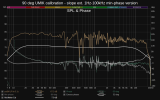
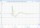
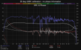
Can't say there's much of a huge difference/impact in my UMIK-1 measurements after I tried to extend the response and create its "minimum phase" version:

1695747907041.png 1695747911480.png

Did I do this right? Seems fine to implement either way.

Hmmmn... this might depend on the microphone unit (and amount of deviation it has) and probably in how you create the min-phase version -- interestingly, the DRC FIR documentation says that we don't need it.
 

Attachments

  • UMIK-1 calibration.zip
    613.9 KB · Views: 27

OCA

Addicted to Fun and Learning
Forum Donor
Joined
Feb 2, 2020
Messages
679
Likes
499
Location
Germany
Can't say there's much of a huge difference/impact in my UMIK-1 measurements after I tried to extend the response and create its "minimum phase" version:

View attachment 314902 View attachment 314903

Did I do this right? Seems fine to implement either way.

Hmmmn... this might depend on the microphone unit (and amount of deviation it has) and probably in how you create the min-phase version -- interestingly, the DRC FIR documentation says that we don't need it.
No, I don't get any significant difference with Umik and its min phase version, either. I was only quite surprized to see a very different phase response with an analog XLR mic and an audio interface. I don't feel confident enough yet to make a point, correct loopback set up with these systems is quite complicated but I will share my results here soon. But my speakers' XO phase correction now seem to be 12dB/oct at each XO frequency rather than inverted polarity 24 and 12 dB/oct corrections I was applying based on Umik measruements.

But as I said, I don't want to make bold statements at this stage. I am still waiiting for some TRS cables delivery to compare them all simultaneously.


PS Earthworks wouldn't supply me with a phase calibration file, either (I asked for it!)
 
Last edited:

neRok

Senior Member
Joined
Oct 7, 2022
Messages
304
Likes
175
Location
Australia
Are you talking about this part?

1695492840359.png


If not, I want to ask if anyone knows why the line is not straight? I've never noticed this before on an unmodified graph.
I wonder if it is because you are sweeping so low (from 0Hz), and noise is getting in to the measurements (and is not being distinguished as noise by the calculations)?
What's going on at ~21Hz in your original measurements? Is that peak a room mode? That would match ~8.2m long room.
Maybe its a good idea to follow what DL-ART does and ignore everything <~25Hz?

The step response looks like this and far from perfect.

03.png


Next let's create minimum phase version and excess phase version of our equalized FR graph using REW.
The step response of minimum phase version graph and phase itself looks great!
I want it too :)

04.png
Your original step response has group delay from the crossover. In REW if you add together some IIR x-o'd curves, you get a similar thing. If you min phase that sum, you get a step like your 2nd example. You can see this as [4] and [5] in the screenshot below. Then I created linear correction filter in rePhase, had to convolve it with [4] in Audacity (because multiplying in REW didn't create the IR as seen with [7] and [8]), then brought that in as [9]. It has some "pre-ringing".
Steps.png

I think the pre-ringing is unavoidable in this situation. Thinking about it practically, the sweep plays all tones "at the same time" (ref'd to t=0). X-overs and room effects make some frequencies late. If you want those frequencies to be "on time", then you need to start playing them early. Hence there has to be some movement on the Step response before the main peak (the main peak being the majority of the rest of the frequencies). I guess what matters is how audible the pre-ringing is, and in bass tones during music it is probably not very. Mids and Highs are probably a different matter.

BTW, the spectrograms ernestcarl posted in #7 show decent room mode ringing at ~60Hz and ~120Hz. His FIR EQ seems to have sorted out ~60Hz, but not so much ~120Hz. Because peaking room modes can be cancelled with high-Q IIR filters, I wonder if applying some IIR EQ before moving to FIR correcting is a good idea? I've not got around to testing this myself yet. And no I don't mean putting some min-phase EQ in the FIR because that doesn't give the same results when using reasonable tap/IR-length limits (because it's Finite, not Infinite).

But my speakers' XO phase correction now seem to be 12dB/oct at each XO frequency rather than inverted polarity 24 and 12 dB/oct corrections I was applying based on Umik measruements.
Have you considered the electrical vs acoustic phase, if a driver is polarity inverted, and perhaps measured each driver with the other disconnected?
 
OP
AudioBoy

AudioBoy

Member
Joined
Jan 23, 2023
Messages
66
Likes
34
if it is because you are sweeping so low (from 0Hz), and noise is getting in to the measurements (and is not being distinguished as noise by the calculations)?

No. I've tried measuring at 10 Hz and 20 Hz, but the "wave ripple" is still there. I believe it's a subwoofer. I'll try to figure this out tomorrow when I have some free time.
This is does not bother me much because I don't hear any pre-ringing effects even after equalization.

This is my main speaker without the sub.
1696056157264.png


What's going on at ~21Hz in your original measurements? Is that peak a room mode? That would match ~8.2m long room.

I have a small room, and according to calculations, the first room mode should be around 60 hertz (61,3 Hz according to the graph). I'm guessing it's the subwoofer which is much louder than the main speaker. If you make it quieter in level, it is much more difficult to equalize it. These enormous dips cannot be compensated by anything. Another thing I plan to deal with is the huge distortion in the bass (about 10 percent in the 20-30 Hz region). My main speakers without a subwoofer are cleaner (about 5 percent) at the same region. This is weird.

Maybe its a good idea to follow what DL-ART does and ignore everything <~25Hz?
Never heard of it. I'll to google what it is.

Your original step response has group delay from the crossover. In REW if you add together some IIR x-o'd curves, you get a similar thing. If you min phase that sum, you get a step like your 2nd example. You can see this as [4] and [5] in the screenshot below. Then I created linear correction filter in rePhase, had to convolve it with [4] in Audacity (because multiplying in REW didn't create the IR as seen with [7] and [8]), then brought that in as [9]. It has some "pre-ringing".
I fixed the crossovers (sub and mains) in rePhase and created a filter for both channels. My best result so far

1696055444232.png


And I'm quite happy with it. Especially if you look at what happened at the very beginning. But the issue of fixing everything in the REW application is still not closed for me. But at this stage I have other issues that need to be resolved. In particular, issues with a comb filter at high frequencies and a dip in the 1 kilohertz region (I assume this is my desk or a SBIR effect).
 

neRok

Senior Member
Joined
Oct 7, 2022
Messages
304
Likes
175
Location
Australia
Never heard of it. I'll to google what it is.
Dirac Live Active Room Treatment. It is new (came out this year) and currently only available on StormAudio processors. Another member posted some impressive results with it. If you read the following thread to the next page, you will see people talk about the lack of correction around 20Hz. https://www.audiosciencereview.com/...oom-treatment-art-by-dirac.40743/post-1723012
(BC = Dirac Live Bass Control)

I'm guessing it's the subwoofer which is much louder than the main speaker. If you make it quieter in level, it is much more difficult to equalize it. These enormous dips cannot be compensated by anything. Another thing I plan to deal with is the huge distortion in the bass (about 10 percent in the 20-30 Hz region). My main speakers without a subwoofer are cleaner (about 5 percent) at the same region. This is weird.
That seems very loud! What model is the sub? Maybe it just doesn't like playing that loud?

Which dips are you talking about? The one at ~45Hz might be fine, because actually its the peak at ~60Hz that makes ~45Hz look low. The dips at ~110Hz and ~220Hz don't look good, and might be SBIR or something. The sub might be able to help the one at ~110Hz.

Have you done a measure of just your speakers and sub individually? I noticed the other day in my tests that if 1 speaker has a problem, trying to fix the stereo response is hard. It's probably best to check each speaker individually and correct any major individual problems that might be caused due to room asymmetry. Do the same for the sub on its own. Then take a stereo sweep of the speakers, and cross that to the sub (with time correction etc). Then make any further corrects to the combined response.
 
OP
AudioBoy

AudioBoy

Member
Joined
Jan 23, 2023
Messages
66
Likes
34
Dirac Live Active Room Treatment. It is new (came out this year) and currently only available on StormAudio processors. Another member posted some impressive results with it.
Cool. thanks
 
OP
AudioBoy

AudioBoy

Member
Joined
Jan 23, 2023
Messages
66
Likes
34
What model is the sub?
Nuemann KH 750. Two of them.

Now it is at minimum gain ~94 dB. The instructions say it should be at 100dB, and that's very loud compared to my settings. So I don't think it is at breaking point right now.
I use the sub in manual mode (without a remote control application via Wi-Fi). But if I remember correctly, using a sub with a remote control program usually gives better distortion results (about 2%). I need to experiment with all this tomorrow.

Which dips are you talking about?
I don't care about 110Hz and ~220Hz, but I'd like to do something with 45Hz. Because this is the best drum bass part :). But I think this is not possible due to the physics of sound and room modes.

Have you done a measure of just your speakers and sub individually?
Long time ago but not now. Will do it tomorrow as part of planned experiments.
 

neRok

Senior Member
Joined
Oct 7, 2022
Messages
304
Likes
175
Location
Australia
Nuemann KH 750. Two of them.
...
Will do it tomorrow as part of planned experiments.
Those subs should be good. So yer go back to basics and make sure they are crossing at the frequency you want, and that they are summing properly. You gotta get the basics sorted before your try EQ the whole system as 1.

If you can make sense of this image, it looks like you might be running the subs with a very low XO frequency and at a very loud level. The black lines are where it seems you have room modes (peaks and nulls).
subs.jpg
 
OP
AudioBoy

AudioBoy

Member
Joined
Jan 23, 2023
Messages
66
Likes
34
In my case, the subwoofer can only be crossed in one mode - 80 Hz.

The subwoofer controls the volume of the main speakers itself. It is designed primarily for use with speakers from the same manufacturer. I use non-Neumann speakers. The volume of the entire system is determined jointly: subwoofers + speakers.

However, I can lower the subwoofer volume (so called LOW-CUT), but then I will get a complete lack of bass below 80 Hz, because a lowered frequency response will lead to huge dips in the bass area.

1696080831839.png


Moreover, in the remote control mode, the subwoofer for some reason lowers the volume of the main speakers (about -6dB), so I prefer the manual control mode, in which the signal is maximum for the main speakers. I have already asked the manufacturer of these subwoofers about the reasons for this behavior on this site. From their point of view, everything is fine, you just need to turn up the volume on the main speakers. Although they don’t say how I can do this separately from the sub, which controls the volume of the entire system. All the speakers they produce are active and each has its own volume control.

My mains are passive so I have an amplifier (for each channel), but it is in bypass mode, that is, the volume is controlled from the DAC through the sub. Therefore, in order not to have dips instead of bass, I prefer to increase the volume of the sub to a level acceptable for further equalization and then push it down with the equalizer to the level of the main speakers. So far this trick is working fine.

1696080940184.png
 

palm

Member
Joined
Mar 4, 2023
Messages
74
Likes
62
I’m not familiar with the recent products; “the sub controls the volume” : you use its digital input and it provides L/R analog signals with a high pass filter? (input mode stereo on the diagram of the backplate)
Low cut is indeed a filter, why not using the “subwoofer gain” instead?
In my case neither the sub and the speakers have a DSP so the chain is mac->usb->RME DAC->balanced analog->O800->O300
 
OP
AudioBoy

AudioBoy

Member
Joined
Jan 23, 2023
Messages
66
Likes
34
Low cut is indeed a filter, why not using the “subwoofer gain” instead?
I'm not exactly sure, because... I don’t remember, but if I remember correctly, the volume of the main speaker will decrease along with the volume of the subwoofer. I could be wrong. I'll find out for sure tomorrow. But I really don't know why I need to decrease the volume of subs.

In my case neither the sub and the speakers have a DSP
Isn't that a Neumann 310 on your avatar? :)
 

palm

Member
Joined
Mar 4, 2023
Messages
74
Likes
62
It’s a Klein Hummel O300, the ancestor !
For the sub volume I was just curious after reading that the sub was controlling the volume of the “satellites” ;)
 

neRok

Senior Member
Joined
Oct 7, 2022
Messages
304
Likes
175
Location
Australia
Therefore, in order not to have dips instead of bass, I prefer to increase the volume of the sub to a level acceptable for further equalization and then push it down with the equalizer to the level of the main speakers
If your subs and speakers are out of time you can get dips because they are cancelling each other at those frequencies (like comb filtering). You don't fix it by trying to "overpower" it. You fix it by time/phase aligning them.

The subwoofer controls the volume of the main speakers itself
This doesn't sound right. The sub should just be passing the signal through, and it might alter the signal (change the gain of what it outputs), but it doesn't "control the volume". So how exactly is your system connected? You mentioned RME Babyface Pro, so if you have that connected via XLR to the subwoofer, then the RME is controlling the volume.

So please describe your connections like something > cable > sub > cable > something > passive-speakers. Do you have 1 channel to 1 sub to 1 speaker?

Moreover, in the remote control mode, the subwoofer for some reason lowers the volume of the main speakers (about -6dB), so I prefer the manual control mode, in which the signal is maximum for the main speakers.
So by remote control mode you mean with an app? And manual is with the switches? But do you still have the "Control Mode" switch set to "Local"? Because that says it disables all the other switches if set to "Network". I didn't read the manual, so I'm not sure what the "Bass Management" switch does either.

"Channel B Input Mode" switch seems to set the crossover. I'm guessing coz you have 2 subs, then that means you have 1 for left and 1 for right connected to the Left/A sockets, and so modes 1,2,4 all seem to give the same same result. So that means the sub will set an 80Hz crossover. This doesn't mean the speakers perfectly play that crossover slope, so that's why you might be getting cancellation errors (because the phase could be very different, and the timing could be way out too). You can adjust the subs phase with the switches, but you can only get up to 315° at 80Hz, which is only 11msec, which might not be enough? Maybe the app lets you set any time delay you want?

This is why you need to sweep the subs and speakers seperately = so you can time align them. But I'm not sure how you will achieve this considering the speakers signal comes from the sub? It's easy to sweep the subs alone, just turn off the speaker amps. But to sweep the speakers alone, perhaps you could turn the gain and gain knob to -12, and output level to lowest (94), and maybe that will be enough to get a usable measure? Or maybe you can mute the subs in the app, but still let the speakers play?

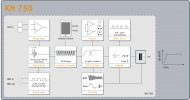
Edit: I found this image on their website, which shows that "Digital Delay" can be set, but who knows how? Maybe via remote control app, or maybe only via network mode?
KH750DSP-Block-Diagrams.jpg
 
Last edited:
Top Bottom