• WANTED: Happy members who like to discuss audio and other topics related to our interest. Desire to learn and share knowledge of science required. There are many reviews of audio hardware and expert members to help answer your questions. Click here to have your audio equipment measured for free!

Crossover Component Recommendations

Ken Tajalli

Major Contributor
Forum Donor
Joined
Sep 8, 2021
Messages
2,081
Likes
1,891
Location
London UK
I would not recommend those for these values indeed. Stil, bipolar caps aren’t exactly super cheap with those voltages.
They are!
just a few pounds each, as opposed to £20 or more for plastic ones. (10uF +)
 

witwald

Senior Member
Forum Donor
Joined
Jul 23, 2019
Messages
480
Likes
505
Out of curiosity, as the crossover network was quite a complex one, I created a circuit model of the Sasandu TX crossover in VituixCAD. In this crude first approximation, I've simply used the voice-coil resistance of each driver as its impedance, and assumed that each driver has a perfectly flat frequency response.

The crossover circuit is shown below:
1696458054372.png

The resulting filtered frequency response curves of the dummy woofer, midrange and tweeter are shown below:
1696458320055.png

The impedance curve obtained with the drivers approximated as constant resistance values is shown below:
1696458470446.png
 

Ken Tajalli

Major Contributor
Forum Donor
Joined
Sep 8, 2021
Messages
2,081
Likes
1,891
Location
London UK
Out of curiosity, as the crossover network was quite a complex one, I created a circuit model of the Sasandu TX crossover in VituixCAD. In this crude first approximation, I've simply used the voice-coil resistance of each driver as its impedance, and assumed that each driver has a perfectly flat frequency response.

The crossover circuit is shown below:
View attachment 316663
The resulting filtered frequency response curves of the dummy woofer, midrange and tweeter are shown below:
View attachment 316665
The impedance curve obtained with the drivers approximated as constant resistance values is shown below:
View attachment 316667
Lovely.
To humour me, can you optain two more curves, for bass and midrange , one with the 900uF removed, another with it bypassed.
For my curiosity ofcourse .
 

Wolf

Addicted to Fun and Learning
Joined
Nov 21, 2020
Messages
572
Likes
611
Location
Indiana
Now that I see the 900uF, yeah, that may be removable. I was commenting on the woofer LCR.
 

witwald

Senior Member
Forum Donor
Joined
Jul 23, 2019
Messages
480
Likes
505
With the 900uF capacitor replaced with a short circuit, the response becomes:
1696460820433.png

There's just a bit of lift in the response of the midrange in the 50–100Hz region. I couldn't see any change in the system impedance curve.

With the 900uF replaced with an open circuit, the response is:
1696461074384.png

There's more lift in the response of the midrange in the 30–150Hz region. There is also a small increase in the impedance peak ay 400Hz.
 

witwald

Senior Member
Forum Donor
Joined
Jul 23, 2019
Messages
480
Likes
505
... a 50Hz possible glitch on a midrange driver...
The manufacturer's response curve for this "midrange" driver is shown below:
1696462400933.png

This driver is a midwoofer, and that 50Hz region should exclusively involve textbook pistonic cone motion. I'm unsure what the measured frequency response curve is actually showing in that low-frequency region. The impedance curve shows no indication of any unusual behavior at 50Hz.
 

Wolf

Addicted to Fun and Learning
Joined
Nov 21, 2020
Messages
572
Likes
611
Location
Indiana
My guess is they nuked the Fs on the midbass to reduce its magnitude and make the xover more effective through there. However, the highpass with a 56uF cap will likely not even allow the mid to think about playing anywhere near there.
 

Ken Tajalli

Major Contributor
Forum Donor
Joined
Sep 8, 2021
Messages
2,081
Likes
1,891
Location
London UK
The manufacturer's response curve for this "midrange" driver is shown below:
View attachment 316679
This driver is a midwoofer, and that 50Hz region should exclusively involve textbook pistonic cone motion. I'm unsure what the measured frequency response curve is actually showing in that low-frequency region. The impedance curve shows no indication of any unusual behavior at 50Hz.
For me! Bypassing the 900uF caps, rules the day. I very much doubt, if it is going to be audible, but it would save 6x£5=£30.
With the money I save, I would double the bass section filters, so each driver gets its own filter, and I wouldn't run the drivers in parallel.
 

ctrl

Major Contributor
Forum Donor
Joined
Jan 24, 2020
Messages
1,633
Likes
6,241
Location
.de, DE, DEU
For me! Bypassing the 900uF caps, rules the day. I very much doubt, if it is going to be audible, but it would save 6x£5=£30.
The LCR filter (with 900µF) in the crossover for the midrange driver is most likely indispensable - as @solderdude and @Wolf already hinted.

The impedance peak around the resonant frequency for the CB midrange cabinet is very pronounced. Due to the slight cabinet damping, the impedance peak should hardly weaken.

At the same time, only a first-order electrical HP filter is used (the 56µF capacitor). The goal could probably be a second-order acoustic filter (this is my guess, since I lack the relevant information, such as near-field measurement of the midrange with XO) - e.g. LR2@400Hz

The problem now is that the driver resonance and the capacitor interact, form themselves a kind of "resonant circuit" (sorry, I'm not an electronic expert), influence the frequency response in an undesirable way and create a peak in the frequency response of the midrange driver.

The LCR filter counteracts this and smooths the frequency response so that the desired filter slope is created.
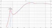
Without the LCR filter the FR and phase frequency response changes a lot, which will most likely lead to a wavy overall frequency response when adding woofer and midrange FR - could be 2-3dB in the 50-100Hz range.

I have simulated the whole thing for the driver used with an 8L CB cabinet, the Sasandu baffle and the 56µF cap (the other XO filter parts, except the LCR filter, are not relevant for the problem). The simulation refers to free field (4pi room, with diffraction effects).
The simulation shows a 20dB higher SPL at 75Hz without the LCR filter (with low cabinet damping) - only measurements can show how big the effects are in reality (more cabinet damping will reduce the effect, but it will likely not go away completely).
1696681755229.png

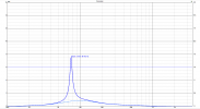
The resonance around 75Hz also means a peak in the group delay and furthermore the midrange driver has to make much more excursion around 75Hz at high SPL than with the LCR filter.
At about 100-105dB@1m SPL of the speaker, the difference in excursion of the midrange driver around 75Hz could look something like this:
1696683020504.png
To save some money, you can also use two bipolar electrolytic capacitors with 470µF + 470µF (or 560µF + 330µF) - would be about 14€ total.

It would be an advantage if you were able to make impedance and FR measurements, since you can then check that the LCR filters really work in the intended frequency range and as intended.
 
Last edited:

Wolf

Addicted to Fun and Learning
Joined
Nov 21, 2020
Messages
572
Likes
611
Location
Indiana
The option of 2x 1800uF polarized in series also exists here, as they may be cheaper and have higher voltage ratings than the audio standard NPE types.

What I am laying out as follows has not been tried on the Sasandu to my knowledge, and would need to be verified for effectiveness should one of these be tried.

The other ways to minimize the Fs spike of the midbass include;
- resistor across the driver, say 40-50 ohms to minimize the sensitivity loss and keep the current requirements low on the resistors. 25W should suffice here.
- added series resistance will add damping to the circuit by way of a resistor or higher DCR coils. A lot of times a slightly smaller gauge coil on a woofer will minimize the effect a bit.
- use some sort of an aperiodic midrange chamber. Since these reduce enclosure Qtc at resonance, they can reduce resonance magnitude really well. Either a single chamber with damped exit, or dual chamber with damped transition. I have the opinion that these kind of chambers yield very good sounding midrange.
 

Waxx

Major Contributor
Joined
Dec 12, 2021
Messages
1,990
Likes
7,924
Location
Wodecq, Hainaut, Belgium
For passive crossovers i always use PP or MKP film caps. They are reliable, relative cheap and have no unwanted impact on sound. Jantzen Crosscap, Dayton Audio DMPC are very good, Dayton PMPC is better because of the smaller tollerances. But in reality, whatever you can find that is relative precis (5% tollerance or smaller) that is a good PP or MKP filmcap coud do the job. Axial caps are mostly preferred, but more from practical point, as most crossovers in diy are point to point wired. A breadboard or circuit board can also be used off course, but for one off's it's more expensive.

Inductors are mostly aircoils of the right gauge, don't get fooled into flatfoil or other special ones, regular copper wire is good enough. The right gauge is way more important.
If an aircoil gets to big or expensive, get a laminated iron core coil, no ferriet ones. They are not as good as aircoils, but not that far of neighter and way cheaper and smaller. The whole technical explenation can be found online why.

Resistors need to be low inductance ones, and rated higher in wattage than what you think will pass trough that resistor. Most use wirewound resistors enbedded in cement or ceramics (the big white ones) and they do the job. There are all kind of expnsive special ones, but they are not better in reality.

In all parts, the lower the tollerances are, the better, and the lower the ESR is also.

That said, this is a perfect scenario for passive analog. Many speakers were build with electrolyte caps, regular metal film resistors and ferrite core inductors, and some of them do sound and measure very good. The right crossover layout (electrically and physically) is way more important than the parts in it. De know that electrolye caps change over time and loose specs and go bad. That is the main reason actually why i avoid them as much as possible, because on sound there is little impact when they are on spec.
 

Rick Sykora

Major Contributor
Forum Donor
Joined
Jan 14, 2020
Messages
3,615
Likes
7,353
Location
Stow, Ohio USA
Wow! Wonder who designed these crossovers? They did not seem to have low parts count or low cost as a target...

The same midrange LCR has a 10 mH inductor that is not likely cheap, small or light either. Maybe they really want you to buy the SB kit version, but it has a 20 mH coil in the woofer filter (and still has comparable LCR on midrange).

Since the TX is open source, any alternative crossovers available?

p.s. did not see that some of the high value inductors were .5 mm wire, so they are not as big as the lower impedance ones. Also means they are not as expensive. see my later post about alternatives.:)
 
Last edited:

Nebbermind

Member
Joined
Jul 23, 2020
Messages
17
Likes
3
I thought it would be good to start off with the base crossover, without all the impedance correction network.
Can always add in the LCR later as a separate board as it is across the drivers and easy to add on without disturbing the base crossover network
 

PKAudio

Member
Joined
Mar 25, 2021
Messages
48
Likes
77
10-30mH inductors with Rdc ~3-4ohm in RLC of woofer or midrange as in Sasandu crossover is the job for ferrite cored coil with the discs and 0.5mm wire (~AWG24). See prices here:
10mH 7euro a piece
It is nothing I would call huge, expensive and heavy.

Same goes for electrolytic capacitor, the prices are the units of euro.
2x470uF is close enough, 8euro a piece

In total ~50eur for two midrange RLCs (and I bet one would find even less expensive options). Compared to the prices of all TX units and good cabinet work, 50euro is nothing.

One has to realize Sasandu is 3way speaker with Fc 300 and 2000 (approximately, I did not study it in details) and as such the crossovers are more complex, require larger values of the components. It is the different world compared to 2way speakers.

Waxx #30: exactly that is the reason for RLC with 900uF. If it was my project, I would definitely try to replace midrange filter C+RLC with LR2, or change the topology, or anything that Wolf suggested to get rid of the RLC and yet achieve proper 6dB summation and phase tracking. For the reasons not to save the expenses at any cost, but because I like optimized crossovers with the least component count doing the right work.
 

Rick Sykora

Major Contributor
Forum Donor
Joined
Jan 14, 2020
Messages
3,615
Likes
7,353
Location
Stow, Ohio USA
Did not find anything in alternative passive crossovers for these but they are new and higher end. Here the (assembled) crossover kit is $2300 for the pair. Admittedly, you may be able to build for less. In any case, if you want to explore options, passive crossovers can get incrementally expensive quickly unless you can properly simulate them (major project). If you do not have the experience or the time, stick to the stock crossover or...

For less could buy some nice Hypex Fusion amps have lots of options to try different crossover variations with only your time as additional cost. If I were investing in building a speaker like the Sasandu (TX), would seriously consider going to active crossovers. :cool:

Are your equipped to measure drivers and the speaker? You mentioned industrial experience, but just trying to understand your background and interest in typical DIY vs BIY (Build It Yourself)? Are you buying or building the cabinets?
 

Karl-Heinz Fink

Active Member
Technical Expert
Joined
May 20, 2016
Messages
112
Likes
489
Hi SC,

the crossover looks like it is done by Daniel Gattig......the parts look like one of his designs. As he knows well what he is doing, it's not wrong to follow it.
Here is the link to the shop in Germany: Lautsprechershop

You can use the Elcaps for the 900uF without problems. ESR is not important with the big inductor and the resistor in series. The 56uF filter cap reduces the level in the region of the LCR working range. No worry, I used those filters during the last 25 years in countless speakers. The Jantzen coils are normally iron dust and that works well in such an LCR filter. The alternative could be a laminated steel core....I would not go for Ferrite, as it goes from good to saturation pretty quickly and we don't have the good Ferrite material we could buy many years ago.

The Jantzen CrossCaps are good. Not crazy expensive, but good sounding. Gattig also got his own brand of caps called Audaphone MKP. Both are Asian-made PP types with low DF factor.

If you are happy to spend some money, you could make the 4.7uF better and use a low inductance resistor. And before somebody starts the discussion again nobody can hear the difference: This is my opinion, not more. OK? Thanks!
The Mundorf ZN type is not bad. It's this one or the classic Supreme type....but the crosscap is already very good. Don't go too crazy

For the 1.2 Ohm, I would parallel 10x 0.4W 12 Ohm good quality Metal film with low TK and low tolerance. That's very cheap to do and works well. 4 watts is enough, but if you want to go safer just use more with a value that gives you the 1.2 Ohm.

Just my 2c :rolleyes:

KH
 

Rick Sykora

Major Contributor
Forum Donor
Joined
Jan 14, 2020
Messages
3,615
Likes
7,353
Location
Stow, Ohio USA
Hi SC,

the crossover looks like it is done by Daniel Gattig......the parts look like one of his designs. As he knows well what he is doing, it's not wrong to follow it.
Here is the link to the shop in Germany: Lautsprechershop

The Sasandu TX or any other SB Acoustics designs do not appear to be sold by Lautsprechershop. The crossover for the Sasandu is very similar and SB claims it was done internally. Not familiar with Gattig. Is he associated with SB Acoustics?
 
Last edited:
OP
S

SmellyCroc

New Member
Joined
Sep 29, 2023
Messages
3
Likes
2
Hi everyone,

Many thanks for all the comments and guidance, it is most appreciated.

Ive actually decided to park the project following the purchase of an ADI-2 DAC/Amp (blame ASR and @amirm) This little box has made me appreciate headphone listening all over again and I’m questioning the need for anything else (I know, a crazy idea)

To be honest, a joiner friend is helping/teaching/rescuing me with the cabinets so the project will continue on that front, for now, as Im enjoying the woodworking.

SC
 

Rick Sykora

Major Contributor
Forum Donor
Joined
Jan 14, 2020
Messages
3,615
Likes
7,353
Location
Stow, Ohio USA
Hi everyone,

Many thanks for all the comments and guidance, it is most appreciated.

Ive actually decided to park the project following the purchase of an ADI-2 DAC/Amp (blame ASR and @amirm) This little box has made me appreciate headphone listening all over again and I’m questioning the need for anything else (I know, a crazy idea)

Sounds like a great purchase regardless of what transducers are involved. Enjoy!

To be honest, a joiner friend is helping/teaching/rescuing me with the cabinets so the project will continue on that front, for now, as Im enjoying the woodworking.

SC

As I would find the Sasandu cabinet challenging too, good to be able to lean on someone experienced with joinery. The Ara TX uses the same drivers and the cabinet is a scaled down Sasandu. Might be a good way to walk before running to building the larger cabinet. :cool:
 
Top Bottom