• WANTED: Happy members who like to discuss audio and other topics related to our interest. Desire to learn and share knowledge of science required. There are many reviews of audio hardware and expert members to help answer your questions. Click here to have your audio equipment measured for free!

Amplifier Output Impedance (Damping Factor) and Speakers

DanielT

Major Contributor
Joined
Oct 10, 2020
Messages
4,828
Likes
4,765
Location
Sweden - Слава Україні
It's hardly rocket science. You can even drive the ouptut stage to a 'negative impedance'. Yamaha did that for a decade (in subwoofers/mini systems) with YST/AST (Yamaha active servo technology). The dedicated HiFi YST speakers came with a cartridge specially configured and you plugged it into the rear of the YST amplifiers. For normal speakers, a flat cartridge was supplied with the amp.

View attachment 176017

Amazing system but never caught on. Could have been a game changer. We ended up selling the amplifiers, systems and speakers really cheaply when they killed the concept after less than a year.

They still use it in the powered subwoofers IIRC.
Audio Pro had something similar, right?

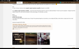
Attached pictures from this thread:


Attachments

  • shot_2022-01-03_13-55-22.png
    shot_2022-01-03_13-55-22.png
    390.7 KB · Views: 69
  • shot_2022-01-03_13-56-06.png
    shot_2022-01-03_13-56-06.png
    479.9 KB · Views: 65

KSTR

Major Contributor
Joined
Sep 6, 2018
Messages
2,778
Likes
6,215
Location
Berlin, Germany
The induced EMF is opposite it polarity to the applied EMF (Lenz’s Law). The lower the amplifier’s output impedance the quicker it will damp the back EMF. Think regenerative braking in Electric Vehicles.
Not quite, correct phrase would have been:
The lower the effective damping resistance (Reff = driver Rdc + XOver + cables + amplifier’s output impedance) the quicker it will damp the back EMF.
It's immediately obvious that the amp can influcence this sum only when its output resistance is signifcant, say, more that 1/10th of the other terms summed.
 

KSTR

Major Contributor
Joined
Sep 6, 2018
Messages
2,778
Likes
6,215
Location
Berlin, Germany
@DanielT,

Some negative output resistance reduces effective damping resistance per above equation. It's a crude form of applying more velocity feedback (the result of more damping) than already inherent in the driver itself. It does work quite well with many drivers if correctly dialed in.
 

Suffolkhifinut

Major Contributor
Joined
Dec 8, 2021
Messages
1,224
Likes
2,027
Not quite, correct phrase would have been:
The lower the effective damping resistance (Reff = driver Rdc + XOver + cables + amplifier’s output impedance) the quicker it will damp the back EMF.
It's immediately obvious that the amp can influcence this sum only when its output resistance is signifcant, say, more that 1/10th of the other terms summed.
Sums it up nicely thanks, lowering the output impedance of the amplifier does make a difference.
Ron
 

Kijanki

Active Member
Joined
Dec 16, 2021
Messages
106
Likes
69
The induced EMF is opposite it polarity to the applied EMF (Lenz’s Law). The lower the amplifier’s output impedance the quicker it will damp the back EMF. Think regenerative braking in Electric Vehicles.
Induced EMF voltage is the same polarity, but current (responsible for braking) is in the opposite direction from the speaker to the amplifier. This current is equal induced EMF voltage divided by total impedance in the circuit - speaker coil + cable + amplifier (all in series). When speaker is about 6 ohm it won't make much difference in braking if amplifier's output impedance is 0.1ohm (6.1ohm total) or 0.01ohm (6.01 ohm).
 

pogo

Major Contributor
Joined
Sep 4, 2020
Messages
1,303
Likes
424
When speaker is about 6 ohm it won't make much difference in braking if amplifier's output impedance is 0.1ohm (6.1ohm total) or 0.01ohm (6.01 ohm).
This is an approach that is idealized and in reality the 6Ohm is not fixed because each turn of the voice coil couples individually and proportionately during movement, so the resistance is distributed.
 

pma

Major Contributor
Joined
Feb 23, 2019
Messages
4,602
Likes
10,771
Location
Prague
Better say the voice coil self inductance is strongly frequency dependent. It is not a constant number.
 

Kijanki

Active Member
Joined
Dec 16, 2021
Messages
106
Likes
69
Better say the voice coil self inductance is strongly frequency dependent. It is not a constant number.
For the woofer it is the lowest at the low frequencies. The lowest impedance is at DC, being about 2/3 of 1kHz rated nominal impedance.
 

Kijanki

Active Member
Joined
Dec 16, 2021
Messages
106
Likes
69
This is an approach that is idealized and in reality the 6Ohm is not fixed because each turn of the voice coil couples individually and proportionately during movement, so the resistance is distributed.
Braking current is inversely proportional to total impedance in the circuit.
 

Suffolkhifinut

Major Contributor
Joined
Dec 8, 2021
Messages
1,224
Likes
2,027
Sums it up nicely thanks,
Ron
Induced EMF voltage is the same polarity, but current (responsible for braking) is in the opposite direction from the speaker to the amplifier. This current is equal induced EMF voltage divided by total impedance in the circuit - speaker coil + cable + amplifier (all in series). When speaker is about 6 ohm it won't make much difference in braking if amplifier's output impedance is 0.1ohm (6.1ohm total) or 0.01ohm (6.01 ohm).
The formula is -e = L x (di/dt) the - indicates the direction of the induced EMF.
 

Kijanki

Active Member
Joined
Dec 16, 2021
Messages
106
Likes
69
When positive voltage is applied to the speaker membrane moves forward. Current inside of the speaker flows from "+" to "-" terminals. To apply braking force to membrane moving in the same direction on its own direction of the current has to be the opposite. It can happen only when induced voltage is in the same polarity, since speaker now is the source and amplifier is the load. Current flows from positive speaker terminal thru amplifier and back to negative speaker terminal. In the speaker current flows from "-" terminal to "+" terminal.
 

Suffolkhifinut

Major Contributor
Joined
Dec 8, 2021
Messages
1,224
Likes
2,027
When positive voltage is applied to the speaker membrane moves forward. Current inside of the speaker flows from "+" to "-" terminals. To apply braking force to membrane moving in the same direction on its own direction of the current has to be the opposite. It can happen only when induced voltage is in the same polarity, since speaker now is the source and amplifier is the load. Current flows from positive speaker terminal thru amplifier and back to negative speaker terminal. In the speaker current flows from "-" terminal to "+" terminal.
They are just terminal markings indicating the correct supply polarity. Under back fed induced EMFs the indicated polarity is incorrect.
 

Kijanki

Active Member
Joined
Dec 16, 2021
Messages
106
Likes
69
They are just terminal markings indicating the correct supply polarity. Under back fed induced EMFs the indicated polarity is incorrect.
The formula you quoted is likely for the circuit with battery switch and inductor. Here back EMF is a result of the motion of the membrane inducing voltage. Again, in order for induced current to brake the motion it has to flow in direction that makes opposite motion of the membrane. If current causing forward motion of the membrane flows from + to - terminals inside of the speaker in order to brake motion of the membrane moving on its own it has to flow in the opposite direction thru the speaker, from - terminal to + terminal. This will only happen if induced back EMV voltage has the same polarity. Current will flow from + speaker terminal thru the amp back to - speaker terminal. Inside of the speaker it will flow from - to + terminals.
 

Geert

Major Contributor
Joined
Mar 20, 2020
Messages
1,955
Likes
3,570
This is an approach that is idealized and in reality the 6Ohm is not fixed because each turn of the voice coil couples individually and proportionately during movement, so the resistance is distributed.
As you already repeated this same message for more than 10 times in different topics (often including the same link to some vague text), can you explain what it means and what the exact impact on speaker driver damping is?

To what do the individual turns of a voice coil couple to?
Why do they couple individually and not as a single coil?
What's the impact on this on the voice coil impedance and driver damping?
Over what is the "resistance distributed"?
 

Suffolkhifinut

Major Contributor
Joined
Dec 8, 2021
Messages
1,224
Likes
2,027
The formula you quoted is likely for the circuit with battery switch and inductor. Here back EMF is a result of the motion of the membrane inducing voltage. Again, in order for induced current to brake the motion it has to flow in direction that makes opposite motion of the membrane. If current causing forward motion of the membrane flows from + to - terminals inside of the speaker in order to brake motion of the membrane moving on its own it has to flow in the opposite direction thru the speaker, from - terminal to + terminal. This will only happen if induced back EMV voltage has the same polarity. Current will flow from + speaker terminal thru the amp back to - speaker terminal. Inside of the speaker it will flow from - to + terminals.
It doesn’t matter Lenz’s law applies to all inductive circuits. To put it another way an inductive load will oppose any change in rise or fall in circuit current. They are also known as ‘Chokes‘ as they will oppose any rise in circuit current.
 

KSTR

Major Contributor
Joined
Sep 6, 2018
Messages
2,778
Likes
6,215
Location
Berlin, Germany
The Voice Coil inductance Le is pretty much irrelevant for damping at low frequencies and also does not dominate Back-EMF in any way.

The terminal voltage of a speaker driver has two additive terms:
- the velocity voltage generated by the voice coil from the current cone movement, no matter what had caused it, plus
- the electric voltage generated along the static impedance of the voice coil (Rdc + Le) from the current flowing through it

From this it can easily be seen that significantly reducing the static impedance increases damping by the following mechanism (whereas going from DF40 to DF800 does not):
The amp impresses a voltage on the driver, the driver responds by generating the velocity voltage. When this velocity voltage doesn't match the amp voltage, the electrical voltage building up across the static VC impedance forces a corrective current to flow.
Then a smaller impedance (by adding in significant negative amp output impedance) gives more current for correction. Factors up to around 3 are easily accomplished.
 
Last edited:

Kijanki

Active Member
Joined
Dec 16, 2021
Messages
106
Likes
69
It doesn’t matter Lenz’s law applies to all inductive circuits. To put it another way an inductive load will oppose any change in rise or fall in circuit current. They are also known as ‘Chokes‘ as they will oppose any rise in circuit current.
Lenz's law only states that the polarity of the induced EMF is such, that it produces a current whose magnetic field opposes the change which produces it. That implies that EMF current has to flow in the opposite direction thru the speaker (to create opposite motion). In order for this to happen polarity of EMF has to be the same (because current now flows not from amp to speaker but from the speaker to amp).

I just conducted experiment with my speakers. I disconnected cables and applied 9V battery + to (red) plus terminal and minus to (black) minus terminal of the woofer. Membrane moved in - my woofers are likely marked backwards. After that I measured voltage on the terminals pushing membrane in. It produced voltage of the same polarity. You can make this experiment yourself. Polarity of the back EMF voltage caused by the motion of the membrane is the same as polarity of the applied voltage to produce motion in the same direction.
 
Last edited:

Suffolkhifinut

Major Contributor
Joined
Dec 8, 2021
Messages
1,224
Likes
2,027
Lenz's law only states that the polarity of the induced EMF is such, that it produces a current whose magnetic field opposes the change which produces it. That implies that EMF current has to flow in the opposite direction thru the speaker (to create opposite motion). In order for this to happen polarity of EMF has to be the same (because current now flows not from amp to speaker but from the speaker to amp).

I just conducted experiment with my speakers. I disconnected cables and applied 9V battery + to (red) plus terminal and minus to (black) minus terminal of the woofer. Membrane moved in - my woofers are likely marked backwards. After that I measured voltage on the terminals pushing membrane in. It produced voltage of the same polarity. You can make this experiment yourself. Polarity of the back EMF voltage caused by the motion of the membrane is the same as polarity of the applied voltage to produce motion in the same direction.
Congratulations you’ve just rewritten one of the Scientific rules. Although your tests leave a little to be desired?
 

Kijanki

Active Member
Joined
Dec 16, 2021
Messages
106
Likes
69
Congratulations you’ve just rewritten one of the Scientific rules. Although your tests leave a little to be desired?
Please conduct this test yourself and speak later. I'm not sure why it is so hard to understand that braking current has to flow in opposite direction to current causing motion (that's what Lenz says). In order for this to happen voltage generated by the membrane motion has to be the same as voltage applied that causes motion in the same direction. You have to think, instead of quoting laws that you clearly don't understand. I had big hopes, that experiment might finally convince you, but I see it is hopeless. I'm out.
 
Last edited:
Top Bottom