• WANTED: Happy members who like to discuss audio and other topics related to our interest. Desire to learn and share knowledge of science required. There are many reviews of audio hardware and expert members to help answer your questions. Click here to have your audio equipment measured for free!

Post Directiva r1 Passive Crossovers here

ctrl

Major Contributor
Forum Donor
Joined
Jan 24, 2020
Messages
1,633
Likes
6,243
Location
.de, DE, DEU
Because it seems to me that depending on the listening distance (as you move closer and further to and from the speaker), designing on the tweeter axis will cause phase differences as the relative distance between your ear and both drive units isn't consistent.
Yes, it makes especially the passive crossover tuning a bit easier.

This is once again a design decision that has to be made during development or at the latest during crossover tuning. But in this case, with normal listening distances, it hardly makes a difference.
 

TimVG

Major Contributor
Forum Donor
Joined
Sep 16, 2019
Messages
1,201
Likes
2,652
Lol thanks, not even in near field applications?

It's all about making sure the drivers sum well. If you were to listen to the directiva (as tested) at say, 50cm at the woofer height, this is what you'd be hearing (minus room effects of course)

1634326049700.png
 

617

Major Contributor
Forum Donor
Joined
Mar 18, 2019
Messages
2,439
Likes
5,393
Location
Somerville, MA
The acoustic center of a woofer varies with frequency iirc, but is roughly around the center of the VC. The DXT tweeter is recessed compared to a normal tweeter, I'd estimate about 1cm back from where most 104mm tweeters are. I would expect that in the Z plane these drivers are pretty close to each other.

Honestly there are so many variables with 3d measurement that what I like to do is use the 3d measurements, load them into VCAD and use active filters to discover the ideal crossover point. Then, I take axial measurements taken from the same point in space (80cm out from tweeter) using the exact same settings, and use those to finalize the crossover (being sure to use ARTA loopback). Then, to confirm the design, I build the thing and measure it in 3d again.

For the most part the only thing I tweak is the padding resistors on the tweeter and or mid.

Generally speaking Z offsets are not going to make a huge difference; they will tilt the treble lobe up or down a bit. Obviously something you want to be aware of, but I think in the days of 2d measurements, designers became obsessed with getting the most perfect phase tracking possible when in reality that phase tracking was only true for one point in space.
 

617

Major Contributor
Forum Donor
Joined
Mar 18, 2019
Messages
2,439
Likes
5,393
Location
Somerville, MA
I don’t know why the tweeter is the design axis, to me it makes much more sense to design in the vocal region so in this case, the woofer mid bass

It's not unheard of for the design axis to be between the mid and tweeter, but generally designers opt for the tweeter being the design axis since the tweeter reproduces the frequency region most sensitive to movement off axis. Going 20 degrees off axis at 200hz doesn't change anything, but at 10K, even a few degrees will cause your response to dip.
 

BenB

Active Member
Joined
Apr 18, 2020
Messages
285
Likes
446
Location
Virginia
In principle, everything is correct so far. Since this is the first time Amir has measured individual drivers for a loudspeaker design, there are a few uncertainties in the data.

It seems that Amir set the NFS so that the reference point for tweeter and woofer was the center of the driver for both measurements.

Therefore, in VCAD, the driver spacing of tweeter and woofer must be entered for the y-axis. We have chosen the center of the tweeter as the listening reference axis. Therefore, the y-value for the tweeter remains 0 in VCAD, and -145mm is entered for the woofer.
View attachment 159239
With the measurement method described above, it is crucial that the distance to the baffle (z-direction) does not change when the microphone is set once at the height of the tweeter and once at the height of the woofer. Therefore, the relative z-axis offset of the sound origins of tweeter and woofer is already included in the measurement (but the y-axis offset not).

Amir is not sure whether he has entered the selected reference points in the Klippel NFS in the z-direction with millimeter precision.
This is still a small uncertainty until someone has either built the first passive crossover or has checked via measurements that the 52µs delay set for the active version corresponds to reality.
Thanks for responding to explain the apparent inconsistency in the treatment of the offsets (z vs y). It's good to know your understanding of the data in consistent with mine, as are the implications for how to simulate a passive crossover correctly. (no z offet... only y)

There are lots of ways to identify the precise acoustic offsets between the drivers. One thing you can do is to play different, synchronized mls signals on each of them (in fact, a backward mls signal is still an mls signal, and can be used for this purpose). When you record the speaker response, you can cross-correlate to find the synchronized impulse response of each driver (or way, in the case of multiple drivers per way). The simultaneous signals may cause a heightened noise floor in your synchronized impulse responses, but you can use that as a reference to align impulses derived from measuring the drivers 1 way at a time (with a lower noise floor).

Alternatively, you can simply play the same measurement signals through both speakers, and record each driver individually, as well as the sum. Then you can go back and calculate the required delay to make the sum of your independent measurements match the measured sum. I typically do a sum and difference (change the polarity on one of the drivers when measuring them together a 2nd time). Then my Z offset is the average of the two delays required to make my independent measurements sum like the measurements taken together. I do have to be careful with my nested line arrays that the Y offsets are factored in.
 

BenB

Active Member
Joined
Apr 18, 2020
Messages
285
Likes
446
Location
Virginia
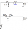
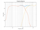
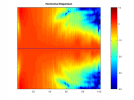
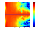
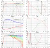
Here's a tweak on 3ll3d00d's crossover. It uses parts available from PE. It's a bit more polite in the midrange, and allows the woofer to play a little higher, which fills in the dip in directivity a little around 3 kHz. It gives up a little efficiency, and uses what I believe is the correct Z offset for the tweeter (which is 0). The cheaper, higher impedance inductor in the woofer circuit tames the peak at 100 Hz a bit. Speaker impedance is a little higher in the crossover region, but the difference is of no consequence.

I developed it in my own software, so although I could post my plots, so I'll post my results, but they wont match the ones others have posted.

Directiva_Passive_Crossover_BenB.png
Directiva_FreqResp_BenB.png
DIrectiva_Horizontal_Sonogram_BenB.png
DIrectiva_Vertical_Sonogram_BenB.png
Directiva_Directivity_BenB.png
Directiva_Impedance_BenB.png
 
Last edited:

Draki

Active Member
Joined
Jan 22, 2020
Messages
115
Likes
149
Location
Macedonia

Attachments

  • Directiva ASR Six-pack.png
    Directiva ASR Six-pack.png
    129.9 KB · Views: 130

Draki

Active Member
Joined
Jan 22, 2020
Messages
115
Likes
149
Location
Macedonia
Anyway, here is my idea of the passive: tweeter delayed with a lattice network, impedance EQ-ed.
 

Attachments

  • Directiva ASR XO-schema-6.png
    Directiva ASR XO-schema-6.png
    17.5 KB · Views: 255
  • Directiva r1 ASR Six-pack.png
    Directiva r1 ASR Six-pack.png
    145.9 KB · Views: 257
  • Directiva r1 PR.PNG
    Directiva r1 PR.PNG
    21.9 KB · Views: 240

McFly

Addicted to Fun and Learning
Joined
Mar 12, 2019
Messages
907
Likes
1,880
Location
NZ
I have downloaded the Directiva files from https://www.audiosciencereview.com/...st-directiva-r1-active-crossovers-here.27124/ : the first post in the "active crossovers" thread, the file attached to it.

Unzipping the files, this is what I got : please note the SPL is at 55 to 65 dB range. No scaling so it is 1:1. Any ideas why is this?
It looks like something went wrong when you unzipped the lot - none of the project files should be moved in the unzipped folder and open vituixcad and open the project file from within vituixcad so that it is pointed to the driver FRD and Z files correctly. When I download and extract + open it I get this:

1634673854569.png
 

Draki

Active Member
Joined
Jan 22, 2020
Messages
115
Likes
149
Location
Macedonia
I opened the raw measurements (bass and tweeter FRs, and impedances), they are txt files and import in V2 without problem.
They look OK, but absolute SPL level (as shown in my case) is too low compared to others' postings here. It works, but I was wondering about it. - I had never used a third-party files before (I am measuring myself) so maybe I did something wrong..?
 

ctrl

Major Contributor
Forum Donor
Joined
Jan 24, 2020
Messages
1,633
Likes
6,243
Location
.de, DE, DEU
I had never used a third-party files before (I am measuring myself) so maybe I did something wrong..?
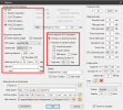
If you have used VCAD before, then there could be problems with options setting.
Unfortunately, VACD does not save all settings for each project separately, so sometimes there can be problems here.
1634683396667.png
And remember the next time to check the options setting again, when you open your projects after saving Directiva project files.

Update: Have tried to write understandable sentences, which was not the case in the first version.
 
Last edited:

kimmosto

Active Member
Joined
Sep 12, 2019
Messages
219
Likes
518
Unfortunately, VACD does not save all settings for each project separately, so sometimes there can be problems here.
Parameters which are not saved to VCAD project file are mostly analysis parameters. At least not related to response data of particular project after responses are succesfully loaded to Drivers tab and project saved. So settings in Options were not the problem for Draki. Problem is that level and phase of measurement data are not either logical standard or documented. Magnitude is about 30 dB lower than drivers' USPL, and phase has excess delay about 3 meters.

Some basic instructions producing measurement data also with Klippel NFS:
* Measure with adequate level to avoid noise e.g. 80-85 dB/1m.
* Scale magnitude of frequency responses to USPL i.e. dB/2.83Vrms/1m no matter actual measurement voltage and distance. Another option is to measure with some common voltage such as 0.5, 1.0 or 2.83 Vrms, and include voltage and distance for each driver as meta data that user could scale responses with parameters on Drivers tab. Assuming that measurement system is SPL calibrated or sensitivity of drivers in project cabinet is otherwise known.
* Excess delay due to distance setting in Klippel is best to remove i.e. phase response should not contain sound flying time from driver's origin (=center point on baffle surface) to virtual or actual microphone. In this case excess delay of 3 meters ~ 8900 microseconds should be removed from phase responses before data is sent to users.
* Frequency range should be at least one octave below and above audio band to avoid response extrapolation and include possible ultra sound break-up of the drivers. VCAD has 5-39794 Hz internal range so sample rate of 88.2k or 96k and export up to 40 kHz is recommended.
* Frequency step should be 48 points per octave or more to avoid excessive/double smoothing and inaccuracies due to interpolation. Too sparse frequency scale leads to wrong result e.g. in benchmarks using narrow band deviation (such as preference rating) and could cause errors to some off-axis calculations. VituixCAD has 48 ppo (beginning at 5.000 Hz) which is barely enough.

Measurement data of directiva seem to meet 0...1/5 of previous. Data works somehow with proper scaling, but measurement instructions might be worth to read also with NFS before starting several XO design projects.
 

BenB

Active Member
Joined
Apr 18, 2020
Messages
285
Likes
446
Location
Virginia
So are there any plans to wire up one of these passive crossovers and compare it to the active stuff?
 
OP
Rick Sykora

Rick Sykora

Major Contributor
Forum Donor
Joined
Jan 14, 2020
Messages
3,620
Likes
7,363
Location
Stow, Ohio USA
So are there any plans to wire up one of these passive crossovers and compare it to the active stuff?

Yes, thanks for reminder. Need to tweak the passive crossover to the newer drivers and will do. :cool:
 
Last edited:

ayane

Active Member
Forum Donor
Joined
Dec 15, 2018
Messages
183
Likes
687
Location
NorCal
Yes, thanks for reminder. Need to tweak the passive crossover to the newer drivers and will do. :cool:
How far along is this effort coming?

If you guys are busy/ haven't started it yet, I can chip in. I ordered the parts to build the speakers and will assemble (and finish!) the cabinets next week. I'll also order the parts for a crossover next week also. I'm leaning a little bit towards the final iteration of @TimVG design (this one) because its PIR tracks V20 of the active crossover (the one Amir measured) very closely when accounting for potential EQ to match the on-axis of V20. More importantly, it's a good compromise between flat PIR and DI while also having flat on-axis without EQ.

If y'all are down, please let me know which crossover to build by early next week if there's a preference, or I'll proceed with the aforementioned plan.
 

TimVG

Major Contributor
Forum Donor
Joined
Sep 16, 2019
Messages
1,201
Likes
2,652
How far along is this effort coming?

If you guys are busy/ haven't started it yet, I can chip in. I ordered the parts to build the speakers and will assemble (and finish!) the cabinets next week. I'll also order the parts for a crossover next week also. I'm leaning a little bit towards the final iteration of @TimVG design (this one) because its PIR tracks V20 of the active crossover (the one Amir measured) very closely when accounting for potential EQ to match the on-axis of V20. More importantly, it's a good compromise between flat PIR and DI while also having flat on-axis without EQ.

If y'all are down, please let me know which crossover to build by early next week if there's a preference, or I'll proceed with the aforementioned plan.

I made another version at one point, which is potentially a bit better, but I don't believe I ever posted it.
You'd have to check with Rick if the vcad simulation can be taken at face value before ordering any parts though. I wasn't involved with R1 so I don't know much of the details.

directiva_TimVGXoverpassive3 XO-schema-1.png

directiva_TimVGXoverpassive3 Six-pack.png
 

KarVi71

Member
Joined
Nov 14, 2019
Messages
63
Likes
68
I'm planing to build the R1 as a passive speaker at one point (I'm in the middle of moving to a new house, so wont have time for many months), but would be very interested in the results.

I find it hard to pick which crossover to build, so some real life results and measurements would be very welcome.
 

ayane

Active Member
Forum Donor
Joined
Dec 15, 2018
Messages
183
Likes
687
Location
NorCal

TimVG

Major Contributor
Forum Donor
Joined
Sep 16, 2019
Messages
1,201
Likes
2,652
Is there a reason for shifting the axis to be the midpoint of the two drivers instead of the center of the tweeter in this version?

To me this is more logical as the phase relationship between the two drivers does not change with distance when you use the midpoint of the two voice coils. If you take one of the units (the tweeter usually) as the acoustical axis, then as you move closer or further the phase relationship changes. If you take the center of one of the units as your reference point, the phase relationship is only fully valid at that exact measurement distance. This won't matter as much in the far field of course, but I prefer the midpoint. It gives me more 'ease of mind'.
 
Top Bottom