• WANTED: Happy members who like to discuss audio and other topics related to our interest. Desire to learn and share knowledge of science required. There are many reviews of audio hardware and expert members to help answer your questions. Click here to have your audio equipment measured for free!

VituixCad or BoxSim

marcop999

Member
Joined
Jun 20, 2023
Messages
20
Likes
4
Hi,

15 year ago I have design a 3 way DIY speakers (76 liters) with these drivers:

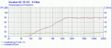
Tweeter: Visaton KE25SC
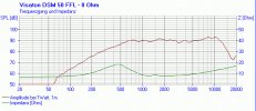
Midrange: Visaton DSM50FFL
Woofer: Monacor SPH250KE

Unfortunately, at that time I was very inexperienced and had not used crossover design software, so by doing some simulations I realised that the frequency response is not flat.

For this reason I like to update my crossover without re-design from zero, just replace some inductors and capacitors and resistors.

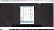
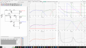
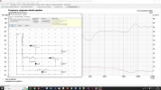
Becouse most of my drivers are Visaton I have used BoxSim and after a lot of work I have found a good compromise with a budget of only 150 Euro of components.

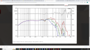
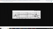
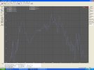
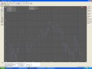
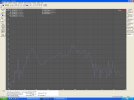
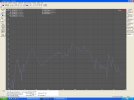
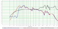
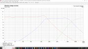
The result seem good becouse the frequency response is flat.

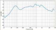
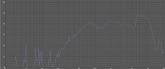
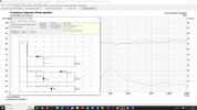
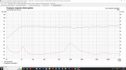
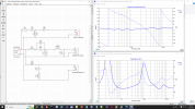
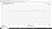
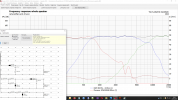
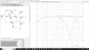
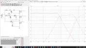
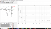
After this I have tried to see what happen with VituixCad and unfortunately there are differences and the frequency response is not flat like BoxSim.

In particular there is an evident bump at 600/700 Hz.

At the moment I am stuck because I don't know who is right: BoxSim or VituixCad or simply there are other options that I don't have set.

Attached there are some screeshots that show what happen.

Do you think that I can trust of BoxSim ? or VituixCad is more accurate ?

Thank you at advance !!
 

Attachments

  • BoxSim_1.png
    BoxSim_1.png
    173.6 KB · Views: 112
  • BoxSim_2.png
    BoxSim_2.png
    142.5 KB · Views: 103
  • BoxSim_3.png
    BoxSim_3.png
    162.2 KB · Views: 98
  • VituixCAD_1.png
    VituixCAD_1.png
    222.5 KB · Views: 96
  • VituixCAD_2.png
    VituixCAD_2.png
    201.9 KB · Views: 92
  • VituixCAD_3.png
    VituixCAD_3.png
    194.2 KB · Views: 108

kemmler3D

Major Contributor
Forum Donor
Joined
Aug 25, 2022
Messages
3,358
Likes
6,885
Location
San Francisco
Vituix is definitely the leading software in the hobbyist space these days. I would tend to trust the results more, but it depends on whether you've set all the parameters of the simulation correctly. I am not qualified to judge that.

I'll just go ahead and say it, because someone will eventually: Why not an active crossover? You may end up spending more on amps... but you can adjust the crossover as much as needed. It's much less risky, especially if you are not sure of the simulation results.
 
OP
M

marcop999

Member
Joined
Jun 20, 2023
Messages
20
Likes
4
Vituix is definitely the leading software in the hobbyist space these days. I would tend to trust the results more, but it depends on whether you've set all the parameters of the simulation correctly. I am not qualified to judge that.

I'll just go ahead and say it, because someone will eventually: Why not an active crossover? You may end up spending more on amps... but you can adjust the crossover as much as needed. It's much less risky, especially if you are not sure of the simulation results.
Because with active crossover is more expensive, more complicate and required more space.

I don't want to change too many things but just a few components in the crossover.

I have a Behringer ECM8000 mic to measure it, but I would like to use it only for a final check to confirm the result not before.
 

voodooless

Grand Contributor
Forum Donor
Joined
Jun 16, 2020
Messages
10,412
Likes
18,385
Location
Netherlands
I have a Behringer ECM8000 mic to measure it, but I would like to use it only for a final check to confirm the result not before.
That’s just silly. It’s like blindfolding yourself before staring a painting, and only removing the blindfold when finished. The result will surely be interesting and artsy, but probably not what you imagined it to be, especially if your not an experienced painter.

As for which one is more accurate.. who knows, you’ll find out if you measure ;)

These programs are quite complex. User error could easily explain any differences as well. That’s why my general go-to is Boxsim. Mostly because I find it easier and faster to use and I’m too lame to learn anything else.
 
OP
M

marcop999

Member
Joined
Jun 20, 2023
Messages
20
Likes
4
I have saved my old measurements, the frequency response it's very wrong, I notice it even when I listen to the speakers.

At the time I thought those peaks were the result of a microphone imperfection but today I know it's not like that.

If I purchase the components and the result is wrong I need to re-purchase again other components.

There are some capacitors and inductors that cost 20/25 Euro / piece.

For this reason I like to understand before purchase any components.
 

voodooless

Grand Contributor
Forum Donor
Joined
Jun 16, 2020
Messages
10,412
Likes
18,385
Location
Netherlands
I have saved my old measurements, the frequency response it's very wrong, I notice it even when I listen to the speakers.

At the time I thought those peaks were the result of a microphone imperfection but today I know it's not like that
Clearly you’re working around a problem instead of fixing it. I’m sure we can figure this out.
There are some capacitors and inductors that cost 20/25 Euro / peace.
That’s why an active system may just be more economical, not less.

And don’t spend money on expensive caps and coils. Especially caps. They don’t add sound quality and if your still experimenting, just buy the cheap ones.
For this reason I like to understand before purchase any components.
Measurements bring understanding.
 

kemmler3D

Major Contributor
Forum Donor
Joined
Aug 25, 2022
Messages
3,358
Likes
6,885
Location
San Francisco
I think you will find more info on DIYAudio, but AFAIK the workflow for building a crossover with Vituix involves measuring each of the drivers one at a time, in the baffle, then importing the measurements to Vituix. At that point you can design the crossover and take into account directivity, FR, phase, and everything at once. Then, with any luck, you can get the xover right on the first try.


I haven't done this, but AFAIK that's the theory.
 

voodooless

Grand Contributor
Forum Donor
Joined
Jun 16, 2020
Messages
10,412
Likes
18,385
Location
Netherlands
I think you will find more info on DIYAudio, but AFAIK the workflow for building a crossover with Vituix involves measuring each of the drivers one at a time, in the baffle, then importing the measurements to Vituix. At that point you can design the crossover and take into account directivity, FR, phase, and everything at once. Then, with any luck, you can get the xover right on the first try.
You’ll also need impedance for a passive crossover. You best measure this as well, but may get away with simulated or traced data, especially since you have two domes that will not depend on an enclosure.
 
OP
M

marcop999

Member
Joined
Jun 20, 2023
Messages
20
Likes
4
I think you will find more info on DIYAudio, but AFAIK the workflow for building a crossover with Vituix involves measuring each of the drivers one at a time, in the baffle, then importing the measurements to Vituix. At that point you can design the crossover and take into account directivity, FR, phase, and everything at once. Then, with any luck, you can get the xover right on the first try.


I haven't done this, but AFAIK that's the theory.
The measurements came directly from BoxSim that match 100% with official visaton graphs.

I have used SPL trace to get the values.

To do another test I have simulated some official Visaton Kits that with BoxSim the frequency response is very flat, but with VituixCad thare are peaks of 4/5 dB on some areas.

To be honest I have found a solution that work good with both, add a RLC network on midrange, but I don't have space on my crossover and without the RLC network with BoxSim simulation the frequency response is more flat.

I suspect that the problem can be a phase shift, but I don't known why there is it and I can't sure if this is the problem.
 

alex-z

Addicted to Fun and Learning
Joined
Feb 19, 2021
Messages
915
Likes
1,695
Location
Canada
You need measurements of your drivers in an actual cabinet. Manufacturer data is not directly applicable to crossover design, as they usually use IEC baffles, which provide much less baffle step loss and diffraction than a real speaker cabinet.


It is also important to consider the directivity of a speaker. A flat on-axis response is only desirable in a speaker with good directivity, your end-goal is a smooth in-room response, which slopes downward as frequency rises and is stable across multiple seats.
 
OP
M

marcop999

Member
Joined
Jun 20, 2023
Messages
20
Likes
4
You need measurements of your drivers in an actual cabinet. Manufacturer data is not directly applicable to crossover design, as they usually use IEC baffles, which provide much less baffle step loss and diffraction than a real speaker cabinet.


It is also important to consider the directivity of a speaker. A flat on-axis response is only desirable in a speaker with good directivity, your end-goal is a smooth in-room response, which slopes downward as frequency rises and is stable across multiple seats.
You are perfectly right.

However I suspect to have an idea about why there are these difference.

BoxSim consider more factors than VituixCad:

1) thiele and small parameters of each driver.
2) Position of of each driver.

I have changed some parameters and now the frequency is similar.
 

voodooless

Grand Contributor
Forum Donor
Joined
Jun 16, 2020
Messages
10,412
Likes
18,385
Location
Netherlands
However I suspect to have an idea about why there are these difference.

BoxSim consider more factors than VituixCad:

1) thiele and small parameters of each driver.
2) Position of of each driver.

I have changed some parameters and now the frequency is similar.
Changed what, where? VirtuixCad should be able to handle these things as well.

BoxSim is made to work with standardized measurements though. They ship with a complete Visaton set to use. This will not be as good as real measurement, but it’s a good guesstimate. I’m not sure how VirtuixCad handles that.
 
OP
M

marcop999

Member
Joined
Jun 20, 2023
Messages
20
Likes
4
I have changed it in BoxSim position of drivers, also I have checked that one capacitor of 3.9uF is not connected good in VirtuixCad and I have fixed it.

In all cases now with graphs that I see, I have understand that both software show similar response, the difference depend by the position of drivers and the volume of box (that is not clear where I can set in VirtuixCad).

In short, I have found where is the problem thank you all for the support.

Now I have another problem with the woofer that is not Visaton but Monacor that not depend by the software. for this I open another discussion.
 

voodooless

Grand Contributor
Forum Donor
Joined
Jun 16, 2020
Messages
10,412
Likes
18,385
Location
Netherlands
Now I have another problem with the woofer that is not Visaton but Monacor that not depend by the software. for this I open another discussion.
The simple way to do this is to measure it independently and use that together with the impedance from the simulation.
 

alex-z

Addicted to Fun and Learning
Joined
Feb 19, 2021
Messages
915
Likes
1,695
Location
Canada
You are perfectly right.

However I suspect to have an idea about why there are these difference.

BoxSim consider more factors than VituixCad:

1) thiele and small parameters of each driver.
2) Position of of each driver.

I have changed some parameters and now the frequency is similar.

VituixCAD uses T/S parameters for the enclosure modelling tool, which you can then feed into the crossover design tool. Also, you can use the merger tool to combine a ground plane + gated measurements, to get reflection free data which extends into the bass region. T/S parameters can change slightly depending on the measurement voltage, so it is best to use actual acoustic data when possible.

VituixCAD has XYZ coordinates for each driver in the crossover design tool. This is useful if you wanted to measure your tweeter + mid-range independently of the bass driver. However, it is best to measure the entire speaker "in-situ" with the impulse responses time aligned, that way you don't need to add XYZ offsets, the positioning data will be included in the measurements themselves.
 
OP
M

marcop999

Member
Joined
Jun 20, 2023
Messages
20
Likes
4
The simple way to do this is to measure it independently and use that together with the impedance from the simulation.
15 years ago I have already measured it, in air and inside a box, with and without filter.

However my enviroment is not it is not suitable for a good measurement becosuse It's a bit noisy and the equipment I have is too cheap for an acceptable measurement.

Apart this all my drivers were measured by an Italian site called dibirama, that I suppose have a better equipment and more experience then me.

I have created a test project in BoxSim, VirtuixCad and Xsim.

The result is that with Visaton drivers the response is similar (original and dibirama) there is only 1 or 2 dB difference with gain.

And this is normal and acceptable.

With woofer the gap is huge, I have ask to the site owner with this response:

"The manufactor measure are notoriously incorrect" and after:
"The gain of woofer is often minor then tweeter and midrange"

With the woofer Monacor SPH250KE the manufactor declare 90dB but looking the graph is more closed to 93dB that is not common and not 90dB

I have checked other brands like seas and scan-speak for 25 cm woofer (10 inches ) all of them are 88/89 dB the graph confirm these vaues.

The measures of dibirama about woofers seas and scan-speak (10 inches ) match with manufactos measures.

The measures of dibirama about woofer SPH250KE are 87/88 dB and are not too far of similar seas and scan-speak woofer of this diameter.

The manufactor SPH250KE measures don't seem real for the reasons I explained earlier.

Now that I known that I can insert XYZ coordinates in VituixCAD I suppose that the result can be very similar on both software.

When I have designed my speakers I made mistakes, the distance between the midrange and tweeter is too far and also the distance between the woofer and midrange is too far.

Please let me known if is better measure the impulse responses time aligned in my case with these mistakes.

At the moment for the woofer Monacor SPH250KE I have used only dibirama frequency response and I don't known if is good idea.

About the final misurations, if BoxSim and VituixCAD show similars result like I see I can expect real result (with all the imperfections of my equipement and enviroment ) that with some different resistor value and other component I can fix easily and the final decision depend by listening and personal taste.

For the woofer the situation is more complicated becouse the manufactor graph seem too different expecially on 200-700 Hz where the box influence is not so important.

What you think ?
 

Attachments

  • sph250ke_spec.png
    sph250ke_spec.png
    715.7 KB · Views: 56
  • sph250ke_dibirama.png
    sph250ke_dibirama.png
    669.3 KB · Views: 50
  • official monacor response.png
    official monacor response.png
    269.1 KB · Views: 53

voodooless

Grand Contributor
Forum Donor
Joined
Jun 16, 2020
Messages
10,412
Likes
18,385
Location
Netherlands
The main issue here is that you seem to have a discrepancy between what you measured (and heard) and what you simulated. That should be the first thing to solve, otherwise, any other changes you make will not give consistent results and you keep on guessing.

I don't see a reason why you should not be able to make measurements with the ECM8000. There are plenty of guides available to do this in a domestic environment. Why not first show us what you previously had? Let's see what problems can be found there, and see how we can solve them.
 
OP
M

marcop999

Member
Joined
Jun 20, 2023
Messages
20
Likes
4
The main issue here is that you seem to have a discrepancy between what you measured (and heard) and what you simulated. That should be the first thing to solve, otherwise, any other changes you make will not give consistent results and you keep on guessing.

I don't see a reason why you should not be able to make measurements with the ECM8000. There are plenty of guides available to do this in a domestic environment. Why not first show us what you previously had? Let's see what problems can be found there, and see how we can solve them.
You have right the main issue is the woofer.

Attached some of old measures and Midrange and Tweeter official measures:

The gap of Midrange and Tweeter can depend not only by imperfections of my equipement but the fact that today I have discovered that he graph of Visaton are changed.

Last year I have re purchase the midrange that sound a bit different, however this is not a problem becouse in my simulation I have both the versions.

When I have measured the woofer with ECM8000 and trueRta the final result is horrible, for this reason I was decide to create a new software and I have used a photometer SL-5868P.

With this software I have compared the frequency response in box in air with filter and without filter.

However these graph don't show me exactly what dB is the woofer and there are too many factors that can influence this.

The distance beetwen the woofer and midrange is 30/35 cm and this can influence the range of 400-700 Hz.

In short is not easy to find the right point to put the microphone to understand the difference of gain between the woofer and midange.

Apart this the crossover inside is wrong and can influence the repsonse a lot.

For this reason I like to start first with the "theory" and after fix the difference if need.
 

Attachments

  • sph250ke4.jpg
    sph250ke4.jpg
    289.6 KB · Views: 40
  • sph250ke3.jpg
    sph250ke3.jpg
    286.3 KB · Views: 44
  • sph250ke2.jpg
    sph250ke2.jpg
    335.7 KB · Views: 37
  • sph250ke.jpg
    sph250ke.jpg
    335 KB · Views: 43
  • sph250ke rss.jpg
    sph250ke rss.jpg
    56.5 KB · Views: 40
  • SPH-250KE (In aria , box 74 chiuso con e senza  reflex) 2000 Hz.jpg
    SPH-250KE (In aria , box 74 chiuso con e senza reflex) 2000 Hz.jpg
    308.6 KB · Views: 37
  • ke25sc_8_fs.jpg
    ke25sc_8_fs.jpg
    135.4 KB · Views: 33
  • KE25SC (no cal) 4 cm.jpg
    KE25SC (no cal) 4 cm.jpg
    115.4 KB · Views: 43
  • dsm50ffl_8_fs.jpg
    dsm50ffl_8_fs.jpg
    138.3 KB · Views: 29
  • DSM50FFL (No cal) 0 cm.jpg
    DSM50FFL (No cal) 0 cm.jpg
    115.9 KB · Views: 46
Last edited:
OP
M

marcop999

Member
Joined
Jun 20, 2023
Messages
20
Likes
4
I think that I have found a good point of start:

Attached the old (2010) and new (2023) crossover with 3 software: BoxSim, VituixCAD, Xsim.

All software show similar result.

I have created 2 different projects: one with all measures from dibirama and one with only woofer measure from dibirama and the rest from visaton.

In all cases the measures from dibirama are similar to Visaton, so I can consider it right.

The new crossover have different advantages:

1) The frequency response is more flat.
2) The woofer polarity is invereted to compansate the phase.
3) The impendance is always upper then 5 ohm.
4) Very cheap upgrade, no need to replace the expensive inductors.

The downside is that on 1 Khz the impendence is very high, but I don't sure if this is problem.

After update this crossover I can start with the misurations that with a bit of lucky can be not too far from the simulation.

What you think ? there are other aspects that I have missing ?

Thank you at adance !!
 

Attachments

  • 2023_Woofer_measure_from_dibirama.png
    2023_Woofer_measure_from_dibirama.png
    162.5 KB · Views: 64
  • 2023_VituixCad.png
    2023_VituixCad.png
    278.5 KB · Views: 55
  • 2023_Crossover.png
    2023_Crossover.png
    174.2 KB · Views: 56
  • 2023_All_measures_from_dibirama.png
    2023_All_measures_from_dibirama.png
    162.4 KB · Views: 50
  • 2010_Woofer_measure_from_dibirama.png
    2010_Woofer_measure_from_dibirama.png
    124.8 KB · Views: 44
  • 2010_Crossover.png
    2010_Crossover.png
    174.4 KB · Views: 43
  • 2010_All_measures_from_dibirama.png
    2010_All_measures_from_dibirama.png
    162.8 KB · Views: 49
  • 2023_Xsim.png
    2023_Xsim.png
    168.8 KB · Views: 51
Last edited:
Top Bottom