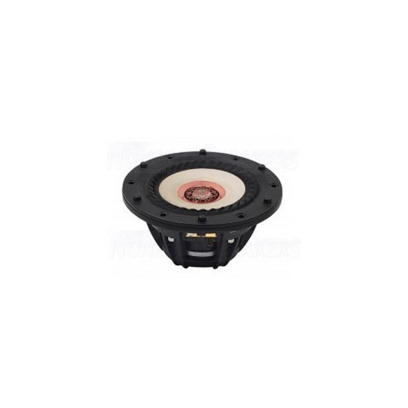
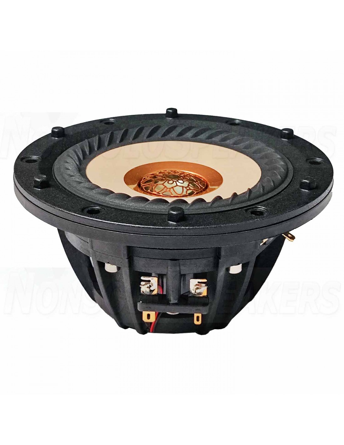
I was referred to Tang Band through a friend in the business, and the president of the company sent me a pair of the W4-2315 4.5" coincident drive units. I recently completed them, showed them at PE's 2023 Speaker Design Competition, and have been thoroughly pleased with the results. These are not yet available on North American soil to my knowledge, and these units are fairly new. The off axis plots they sent me were taken Jan 4, 2023. I only included data herein that I took myself.
Name Monoculus arises from the daisy flower affiliation and the fact that oculus relates to ‘eye’; both of which relate to the look or aesthetic as well as function of a coaxial drive unit. The Tang BandW4-2315 (2315) coincident driver used herein is specially designed to try and minimize or suppress problematic hindrances such drive units usually employ. To keep the active motion of the midrange portion of this driver relatively low requires instead the addition of a comparable woofer to dredge the both deep and moving bass lines. I chose the Tang Band W6-1139SIF (1139) for this task. This driver is small enough to reach high enough in the lower midrange area, as well as not requiring a lot of box volume to yield low enough bass extension.
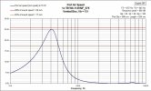
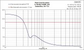
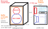
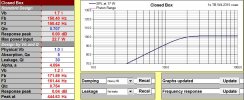
Since I had cabinets I had already made that utilize replaceable baffles, I chose to make this 3way combo work within this size constraint. I call this my VersaBox, and it has a volume of just over 15 liters to work with and keep losses from bracing, mounts, crossover parts, and drivers to a minimum. In ~13.5 ltrs after subtracting 1 liter for the midrange chamber, the 1139 will yield an F3 below 40Hz for tunings below 50Hz with heavy fill. The 2.5” port diameter is required to keep vent mach noise at minimum, and tunes to 47Hz. The port outer exit has a 1” roundover. By using said VersaBox, I have a limited depth requirement that can’t be exceeded, and I chose to keep the inner end of the port more than 1” away from the back of the midrange chamber housing. I also used a wool-felt-lined 4” PVC end-cap for the chamber. This then required the use of a thicker baffle material to keep the drivers’ relative positions further removed from the cabinet volume.
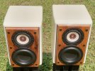
My home has an old outbuilding farm barn that has seen better days. My father (mainly) and I have slowly worked to bring it down so that it does not fall down onto my adjacent garage. In this process of bringing down this structure that was raised in 1896, a plethora of old wood supplies has come to me. I selected a piece of floor joist that is roughly 10.5” wide x 2” thick by length required of old and hard white oak. I had to shave the rot off the edges, square up the dimensions, and flatten the facing curves. I ultimately did the last step 3 times due to the boards cupping twice before I coated and sealed with epoxy. I initially had the driver mounts CNC’d, and then basically had to start over and recut them after the boards moved. Suffice to say, much work was done to get them in a usable state. End result size was just less than full width of my VersaBox inset rebates, but ultimately still looks good to the eye. Normal baffles used in this box are 12 7/8” x 8.5” and ¾” thick. The Oak is 1.75” thick for comparison. I finished the Oak in Danish Oil and followed with oil based polyurethane for the visible dimensions. The rear non-visible half is just coated in epoxy.
The Main portion of the 0.75” thick MDF VersaBox was before this, unfinished, save for 2 coats of epoxy and a light sanding. This left the surface easy to prep for paint. I used Krylon Fusion Primer+Paint for the base white, followed with Duplicolor Effex for a metallic shimmer, and ended with Duplicolor 1K clear gloss. Note that I have glazed over a bunch of prep steps, sanding, sanding, and more sanding, as well as the problems encountered during this process and the dry times inherent. Arduous is definitely the word, but worth the trouble for the results. I finished them before taking measurements so that I would get them done and not have to take them apart again.
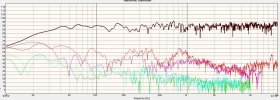
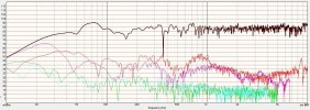
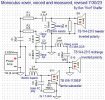
I used the Smith and Larson WT2 for impedance measurements as well as T/S, and the Dayton Omnimic for the frequency responses, harmonic distortion plots, et al. Off axis horizontal plots were extensively taken. Crossover modeling was done with my late friend Jeff Bagby’s Passive Crossover Designer Microsoft Excel based spreadsheet suite. I used Bill Waslo’s Xsim software to plot the off axis curves and draw the crossover schematic. I did not do a polar plot or color map, but I feel the multiplot I posted covers most of the data required. Most treble rolloff is -70 degrees horizontal, and the grey dip is the reverse null.
Resulting crossovers came to 400Hz LR2 and 4kHz LR4 respectively, and utilized 14 component parts to get the job done. Crossover boards are 6” x 7”, and stacked to about 4.25” thick at the most. Due to the component types used, they are also roughly four to five pounds of heft. The midrange breakup on the 2315 was measured as more benign than the spec sheet shows, and therefore a simple 3rd order electrical lowpass sufficed. However, the cavity resonance of the midrange in its chamber came to about 30 ohms with a Q of 1.0, so I had to take care in removing it in the network. I initially tried an LCR series notch, but omitting the R component and relying purely on the coil’s DCR with the additional cap was all that was required to suppress it heavily, and impedance remained benign. This meant a single cap could be simply used as the highpass component. Being that the tweeter is only a 20mm, I also used the midrange highpass to cascade into the tweeter section of the crossover for more protection. The crossover for the tweeter (post-cap) consists of a 2nd order electrical network, and series fore resistor and after shunt resistor. The resistor across the tweeter was added to aid in Fs suppression, as even though the Fs is minute in magnitude, it seemed to be audible without it. The woofer was simple with a 3 component damped 2nd order lowpass. Harmonic distortion is very low for the tweeter, and low enough for the midrange and woofer that it should not be very audible in their utilized bandwidths.
I did play with the various styles of using coaxials in terms of placement, facing direction, whether to optimize for 10-15 degrees off axis or for on-axis, etc. I found I could not lift the top octave for facing straight forward use because they always sounded bright in this application. The normally present dips in the tweeter response that are due to the waveguiding midrange cone are very narrow for the 2315, and really vary in orientation as you change the applied toe-in or not. I found that I didn’t find the treble response unpresentable in any facing placement direction, nor did it really get worse in response until beyond 60 degrees off axis to the point of being audible. I typically have them positioned where I can look down the inside side of the cabinets at the listening position, or toed-in but not to the point of having them facing the center of my skull.
The result is a fairly uniform directivity, small but not diminutive stand mount monitor speaker with about 80-81dB/2.83VAC sensitivity, fairly low inherent distortion, 4 ohm impedance, bass to F10 of 25Hz, and a clean and detailed sound pallet. I have to say that these really surprised me at how resolving they can be in terms of complex music. They are very coherent, image very well, and soundstage is not small. I feel they are one of the more resolving and pleasing designs in my growing repertoire. I have been enjoying them immensely. They are also very appealing visually due to the old wood baffles and smooth metallic white gloss paint job.
A few weeks ago now, at the Parts Express sponsored Speaker Design Competition in August of 2023, these were judged by 3 professionals in the industry, and netted a score of 147 out of 180 total points. This was in a tie for 2nd place initially, and there was also a tie at 150 points for 1st place. Due to tie breakers, this made this entry’s finale to be 4th place, but also totally valid to state it tied for 2nd place.
I also would like to thank Tang Band for the opportunity to work with the W4-2315 drivers. The experience was very favorable for me, and their support of their product was fantastic.
Thanks for looking,
Wolf
Thanks to Bill for the photo...
Attachments
-
 1139VersaMonoculus_Mach.jpg92.1 KB · Views: 339
 -
 1139VersaMonoculus_Xmax75W.jpg80.3 KB · Views: 323
 -
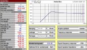 1139VersaMonoculus50Hz.jpg134.8 KB · Views: 337
 -
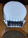 20230624_195551.jpg206.3 KB · Views: 423
 -
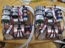 20230729_213635.jpg361.7 KB · Views: 427
 -
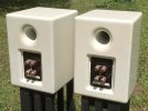 20230802_143618.jpg235.9 KB · Views: 439
 -
 20230802_143914.jpg355.4 KB · Views: 464
 -
 MonocL0-HD.jpg135.5 KB · Views: 520
 -
 MonocR-0-1_12oct_2pt9VAC.jpg69.7 KB · Views: 459
 -
 MonoculusBox.png30.7 KB · Views: 423
 -
 MonoculusR0HD.jpg134.5 KB · Views: 478
 -
 MonoculusXoverRevision1.jpg56.3 KB · Views: 525
 -
 MooculusR_0-75DegH.jpg104.5 KB · Views: 495
 -
 W4-chamber.jpg94.8 KB · Views: 429

