• WANTED: Happy members who like to discuss audio and other topics related to our interest. Desire to learn and share knowledge of science required. There are many reviews of audio hardware and expert members to help answer your questions. Click here to have your audio equipment measured for free!

sergeauckland

Major Contributor
Forum Donor
Joined
Mar 16, 2016
Messages
3,460
Likes
9,163
Location
Suffolk UK
In an amplifier that wants to avoid crossover distortion, there has to be some overlap at the zero crossing.
There doesn't, as per Peter Blomley's design in Wireless World in the early 1970s, but the additional complications aren't worth it compared with having just the right amount of standing current.

S
 

SIY

Grand Contributor
Technical Expert
Joined
Apr 6, 2018
Messages
10,511
Likes
25,350
Location
Alfred, NY
I might be wrong, but I believe the vintage McIntosh MC275/240 amplifiers ran in class B and they got away with it because of the elaborate output transformer. Anyone know for sure?

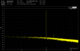
I just ran across this on my hard drive - this is the distortion of my MC240 at its rated 40 watts:
Also, the other tube amps running near Class B are various sweep tube amps from Berning, starting with the Audionics BA-150 back in the late 1970s. I've designed and built several amps using that basic principle, and you can get excellent performance (for a tube amp!) and cool running (for a tube amp!) that way.
 

audio2design

Major Contributor
Joined
Nov 29, 2020
Messages
1,769
Likes
1,832
In theory, class B is when you have no quiescent current going through the output devices. But we have to acknowledge that if you have 5mA or 10mA of quiescent current, that amplifier will run most of the time (99.99%) in class B when you listen to music at a normal level. So yes, in theory this is not textbook class B but during normal operation it works in class B.

Class AB means the devices conduct for more than 1/2 cycle not how much more. You have low bias AB and high bias AB but still AB. A single device conducting means a single device conducting. Whether class B or AB is purely based on what happens during the 0 crossing region. When you look at Vbe or Vgs on the transistors the additional voltage swing to maintain that 5 or 10mA is not insubstantial
 
OP
H

horias2000

Active Member
Forum Donor
Joined
Apr 7, 2021
Messages
157
Likes
204
Location
Cluj-Napoca, Romania
Class AB means the devices conduct for more than 1/2 cycle not how much more. You have low bias AB and high bias AB but still AB. A single device conducting means a single device conducting. Whether class B or AB is purely based on what happens during the 0 crossing region. When you look at Vbe or Vgs on the transistors the additional voltage swing to maintain that 5 or 10mA is not insubstantial
I think that we all agree what the classes mean :). It's only that D. Self has adapted the notion a bit.

This is his definition of class B:
"My definition of Class-B is that unique amount of bias
voltage which causes the conduction of the two output
devices to overlap with the greatest smoothness and so
generate the minimum possible amount of crossover
distortion. For a single pair of output devices the quiescent current will be of the order of 10 ma for a CFP
output stage, or 100 mA for the EF version. With
bipolar transistors, collector current tails off exponentially as Vbe is reduced, and so the conduction period
is rather arguable, depending on what current you
define as ‘conducting’."
 

audio2design

Major Contributor
Joined
Nov 29, 2020
Messages
1,769
Likes
1,832
I think that we all agree what the classes mean :). It's only that D. Self has adapted the notion a bit.

This is his definition of class B:
"My definition of Class-B is that unique amount of bias
voltage which causes the conduction of the two output
devices to overlap with the greatest smoothness and so
generate the minimum possible amount of crossover
distortion. For a single pair of output devices the quiescent current will be of the order of 10 ma for a CFP
output stage, or 100 mA for the EF version. With
bipolar transistors, collector current tails off exponentially as Vbe is reduced, and so the conduction period
is rather arguable, depending on what current you
define as ‘conducting’."

Yes a little bit of 'Self" importance there. He was also the first to discover the distortion mechanisms in amplifiers ... cause there were not hundreds of engineers working on op-amps at 10's of companies at that time and prior.
 
OP
H

horias2000

Active Member
Forum Donor
Joined
Apr 7, 2021
Messages
157
Likes
204
Location
Cluj-Napoca, Romania
Yes a little bit of 'Self" importance there. He was also the first to discover the distortion mechanisms in amplifiers ... cause there were not hundreds of engineers working on op-amps at 10's of companies at that time and prior.
Well it's one thing to work at a company to design a product and another thing to actually write a book and explain to everybody what issues you found and what the solutions are. I also work in a company and we design electronic products and we often run into issues and we investigate and solve these issues. We do not even properly document the solutions so other teams won't have to reinvent the wheel again and again. I agree that the information in his books is not new and it is present in other books/articles but what I like about his books is that all the information is in one place and it is presented in an easy to read manner. And whether we agree or not on his definitions of the classes, the books do really contain a lot of good information in a practical approach.
 

sergeauckland

Major Contributor
Forum Donor
Joined
Mar 16, 2016
Messages
3,460
Likes
9,163
Location
Suffolk UK
I think that we all agree what the classes mean :). It's only that D. Self has adapted the notion a bit.

This is his definition of class B:
"My definition of Class-B is that unique amount of bias
voltage which causes the conduction of the two output
devices to overlap with the greatest smoothness and so
generate the minimum possible amount of crossover
distortion. For a single pair of output devices the quiescent current will be of the order of 10 ma for a CFP
output stage, or 100 mA for the EF version. With
bipolar transistors, collector current tails off exponentially as Vbe is reduced, and so the conduction period
is rather arguable, depending on what current you
define as ‘conducting’."
As much as I admire Doug Self, and I really do, I think his definition of Class B is actually at odds with everyone else's. If an amplifier has the optimum amount of standing current, then it's a very well designed Class AB amplifier, not Class B. Pure Class B has for years been defined as having no standing current. Given the practical difficulties in reducing crossover distortion in Class B amplifiers, it's little surprise that pretty much all amplifiers are in some form of Class AB, most lightly into Class A, a few heavily into Class A. Pure Class A amplifiers are also possible, but they have zero load tolerance as the standing current has to be adjusted for a minimum load, and any reduction in load impedance will either result in the amp going into Class B ( and therefore no longer being Class A) or the amp clips as it runs out of current. The famous Linsley Hood Class A amp is of this second type as it has no means of turning on more current, the standing current is all you get. Musical Fidelity "Class A" (and I think Krell) amps are of the former type, staying in Class A only for a defined range, but smoothly going into Class AB outside that range.

S
 

audio2design

Major Contributor
Joined
Nov 29, 2020
Messages
1,769
Likes
1,832
Well it's one thing to work at a company to design a product and another thing to actually write a book and explain to everybody what issues you found and what the solutions are. I also work in a company and we design electronic products and we often run into issues and we investigate and solve these issues. We do not even properly document the solutions so other teams won't have to reinvent the wheel again and again. I agree that the information in his books is not new and it is present in other books/articles but what I like about his books is that all the information is in one place and it is presented in an easy to read manner. And whether we agree or not on his definitions of the classes, the books do really contain a lot of good information in a practical approach.

They do, and have created a whole DIY community that speaks in acronyms that most people don't use :)
 

audio2design

Major Contributor
Joined
Nov 29, 2020
Messages
1,769
Likes
1,832
As much as I admire Doug Self, and I really do, I think his definition of Class B is actually at odds with everyone else's. If an amplifier has the optimum amount of standing current, then it's a very well designed Class AB amplifier, not Class B. Pure Class B has for years been defined as having no standing current. Given the practical difficulties in reducing crossover distortion in Class B amplifiers, it's little surprise that pretty much all amplifiers are in some form of Class AB, most lightly into Class A, a few heavily into Class A. Pure Class A amplifiers are also possible, but they have zero load tolerance as the standing current has to be adjusted for a minimum load, and any reduction in load impedance will either result in the amp going into Class B ( and therefore no longer being Class A) or the amp clips as it runs out of current. The famous Linsley Hood Class A amp is of this second type as it has no means of turning on more current, the standing current is all you get. Musical Fidelity "Class A" (and I think Krell) amps are of the former type, staying in Class A only for a defined range, but smoothly going into Class AB outside that range.

S

It's even difficult in my mind to classify Blomley's amplifier as pure Class-B, but most people who have designed circuits for a living look at the claim, then look at the circuit and go "whatever" as in call it what you like, it is how it operates that matters.
 

mhardy6647

Grand Contributor
Joined
Dec 12, 2019
Messages
11,405
Likes
24,755
As much as I admire Doug Self, and I really do, I think his definition of Class B is actually at odds with everyone else's.
I thought Class B, by definition, meant the non-conducting device was in full cutoff.
Kinda like virginity. Kinda a binary condition.
Maybe I was misinformed -- about Class B, that is.


quote-capt-renault-what-on-earth-brought-you-to-casablanca-rick-blaine-my-health-i-came-to-humphrey-bogart-76-54-49.jpg
 

audio2design

Major Contributor
Joined
Nov 29, 2020
Messages
1,769
Likes
1,832
I thought Class B, by definition, meant the non-conducting device was in full cutoff.
Kinda like virginity. Kinda a binary condition.
Maybe I was misinformed -- about Class B, that is.

Most definitions are conducts for 1/2 cycle. Blomley's amp "technically", at least in a perfect world does this, but the non-conducting device is not cutoff.
 

sergeauckland

Major Contributor
Forum Donor
Joined
Mar 16, 2016
Messages
3,460
Likes
9,163
Location
Suffolk UK
Most definitions are conducts for 1/2 cycle. Blomley's amp "technically", at least in a perfect world does this, but the non-conducting device is not cutoff.
Yes that's true, but whilst conducting, it has zero signal on it, as the drive to each half of the output is unidirectional. As I've said before, a lot of effort to avoid class AB. I have never built one of those amps, and I wonder how stable the unidirectional drive is although a diode shouldn't change much. Nevertheless, never thought it made sense compared with any number of competent Class AB amps.

S
 

audio2design

Major Contributor
Joined
Nov 29, 2020
Messages
1,769
Likes
1,832
Yes that's true, but whilst conducting, it has zero signal on it, as the drive to each half of the output is unidirectional. As I've said before, a lot of effort to avoid class AB. I have never built one of those amps, and I wonder how stable the unidirectional drive is although a diode shouldn't change much. Nevertheless, never thought it made sense compared with any number of competent Class AB amps.

S

Six of one, half a dozen of others. Typical AB has distortion when the devices cuts off. Blomley in theory avoids this sort of like the blameless Self amplifier. Potential for instability and DC offset control or AC coupling. Is what it is.
 
OP
H

horias2000

Active Member
Forum Donor
Joined
Apr 7, 2021
Messages
157
Likes
204
Location
Cluj-Napoca, Romania
So I managed to assemble the power supply and measure the power amplifier powered from it. The power supply uses 2x10.000uF caps for each channel. Looking at the spectrum, I might want to add more capacitance or have a look at the design to see if I can increase the PSRR. The design itself has a very good PSRR but I guess this is what you get when using unregulated power supplies. For class A operation (first image) it definitely needs more capacitors on the power supply. I also finished the Pre-amp and will post some measurements shortly. The conclusion is that the power supply generated noise shrinks the SINAD from a respectable 91dB (class A) to 74dB. So this comes to confirm one again the importance of the power supply. In the case or unregulated power supply I guess that you can only increase the capacitance on each rail. I will experiment a bit to see what effect this has. Using regulated power supplies for a class A amplifier doe snot seem like a good approach. Another option would be to use a voltage regulator to power the input stage of the amp. In the book, D. Self finds out that most of the power supply noise comes into the amplifier via the negative rail. That is the reason why the input stage has am RC filter on the negative rail. Might try to modify this and add an LDO to see if this bring an improvement or not.

PA_LEFT_5W_8ohm_classA.png


PA_LEFT_5W_8ohm_classB.png
 
Last edited:
  • Like
Reactions: SIY
OP
H

horias2000

Active Member
Forum Donor
Joined
Apr 7, 2021
Messages
157
Likes
204
Location
Cluj-Napoca, Romania
I've built and tested the preamplifier based on the Precision Preamplifier. The results can be seen below. I think this is really good performance and THD is probably limited by the QA401.

First image shows the spectrum for a 1kHz tone. Tone controls were active. So noise will decrease a bit if I select tone defeat of source direct. This basically takes the HF/LF filters out of the circuit.
PRE_left_gain_0.png


This is the same as above but with the actual regulated power supply. Still a bit of 50HZ and its harmonics are present. Not ideal but not audible either. Might want to have a look at the power supply. This was measured at MAX gain (9Vrms output)
PRE_LEFT_MAX.png


This is the frequency response with tone defeat / source direct enabled. Pretty flat.
PRE_FR_defeat.png


And this is with the LF and HF sections set to max gain (10dB). The cutoff frequency can also be adjusted in this preamp.
PRE_FR_H+10_L+10.png


Next I will focus on the PHONO preamp and will post the results maybe today or tomorrow.
 

Attachments

  • PRE_direct.png
    PRE_direct.png
    65.1 KB · Views: 61
  • Like
Reactions: SIY
OP
H

horias2000

Active Member
Forum Donor
Joined
Apr 7, 2021
Messages
157
Likes
204
Location
Cluj-Napoca, Romania
I finished the PHONO preamp and below are the spectrum with 1kHz tone and the frequency response. This is as good as it gets for PHONO preamps with the op-amp (LM4562/LME49720).

PHONO_pre_THD.png


PHONO_pre_FR_1.png
 
OP
H

horias2000

Active Member
Forum Donor
Joined
Apr 7, 2021
Messages
157
Likes
204
Location
Cluj-Napoca, Romania
I now stared looking into this project as I'm done (for now) with the KT88 amp :)

There are two main items I wanted to tackle:
  1. PSRR of the power amplifier
  2. The high 2nd order harmonics in class AB

For the PSRR there are several areas where I tried to improve the circuit besides the obvious one of increasing the capacitance of the power supply output filter. I'm using now 2x10000uF. After a few attempts that did not yield any improvements, I tried using a SMPS that I bought a while ago for this precise task (https://www.audiophonics.fr/en/smps...reh-power-supply-module-300w-30v-p-14063.html). This is a +/- 30V - 300W resonant power supply. This got rid of the 50Hz (and its harmonics) as expected (see the images below).

Now moving on to the 2nd order harmonics, I got a big surprise. As I was trying all sorts of things to try and identify where the imbalance in the circuit was (as far as I know, 2nd order harmonics are generated when the amplifier is not symmetrical. Let's say that the positive cycle of the sine is a bit different from the negative one or vice-versa) I noticed that I had a lot of variations from just moving things around. I initially had the 2nd harmonic at -70dB and after moving the wires and the equipment around I had -80dB. I then started moving around the input cable (coming from the output of the QA401 and going to the input of the power amplifier). This is where I got a huge surprise. There were positions where the 2nd harmonic got below -100dB. I tried using another coax wire for the input of the amp but I got the same behavior.
I don't know what to believe now. I guess that the amp is performing this good and that there is an issue with my setup. I have no other explanation for this. Bellow you can see the THD in class AB for 1W and 5W.

Class AB - 1W into 8OHM
SMPS_20000uF_class_B_new_input_cable_best position_3.png


Class AB - 5W into 8OHM
SMPS_20000uF_class_B_5W_new_input_cable_best position_3.png


This is the measurement before moving the input cable around:
SMPS_20000u_class_B_20kHz.png


Now, with a THD+N (SINAD) of around -92dB, this lands very close to Amir's "excellent" category. This measurement is probably limited by the QA401 as well. In class A I get the same result of -92dB, although I can see that the harmonic content is a bit better.

Class A - 5W - 8OHM load
SMPS_20000u_class_A_220p+1k6_to_GND+220p_Cdom_WIMA_FILM_moving_analyzer_around_best_case.png


As I'm a bit confused about the results, I'm looking at measuring using other equipment to see if this behavior is the same or not. I'll see if I can find a Cosmos E1DA around or I'll look to buy one. If you guys have any suggestions for why this THD measurement varies so much with the position of the cables, I'll be glad to hear them. I'm now doubting the THD measurement I did on the tube amp I just built :)
 

SIY

Grand Contributor
Technical Expert
Joined
Apr 6, 2018
Messages
10,511
Likes
25,350
Location
Alfred, NY
Often, these issues are caused by probe connections.
 
OP
H

horias2000

Active Member
Forum Donor
Joined
Apr 7, 2021
Messages
157
Likes
204
Location
Cluj-Napoca, Romania
Mystery solved! I found the issue I had with the measurement setup. I overlooked one very important aspect of the QA401 analyzer, that all BNC connectors share the same ground and are not isolated from each other. The inputs and output are isolated from the enclosure and from the USB ground but not from each other. This is the same as for oscilloscopes but somehow this slipped my attention and I connected the ground on the amplifier PCB for both the input cable and for the output one. So I had a ground loop that severely degraded the THD and THD+N measurements. What I did, I removed the ground of the coax cable connecting the output of the amplifier to the input of the QA401 analyzer. In this way the GND connection is done only through the input cable. The results can be seen below.

Class AB - 1W
SMPS_20000u_classB_1W_one_gnd_to_qa401.png


Class AB - 5W
SMPS_20000u_class_B_one_gned_to_QA401.png


And another measurement for class AB - 5W and 96kHz bandwidth to see if the switch mode power supply introduces any nastiness at higher frequencies.
SMPS_class_B_96kHz_5W.png


The conclusion is that the amplifier itself has excellent performance in class AB and there is very little (if any) difference when it runs in class A. Secondly, it is pretty clear that using a switching power supply is more than adequate. It will significantly improve the THD+N figure due to the lack of 100Hz (and its harmonics). The THD+N is now very close to Amir's blue category and it will probably land in it with a better analyzer. Maybe it's time to buy an E1DA Cosmos analyzer....hmmmm. I still have a few ideas on how to improve the THD even more but I will need a better method of measuring the THD if I want to improve it.
Another conclusion is that I have to redo all the measurements I did in the past (including the ones for the tube amp) with the correct measurement setup :).
 
Top Bottom