• WANTED: Happy members who like to discuss audio and other topics related to our interest. Desire to learn and share knowledge of science required. There are many reviews of audio hardware and expert members to help answer your questions. Click here to have your audio equipment measured for free!

Philharmonic BMR Speaker Review

R Swerdlow

Member
Joined
Jun 9, 2020
Messages
74
Likes
114
It does adress it, because the question has no single number answer, as masking is frequency dependant, which means H2 and H3 don't have the same audibility limit.
Perhaps I'm not being clear enough.

I'm asking what correlations exist between distortion measurements of speaker drivers and human perceptions of acceptable or objectionable sound quality.

And, as you mentioned, perceptions of sound quality can vary with frequency and H2, H3, etc. But without correlating measured distortion with perceived sound quality, the distortion measurements, alone, don't provide an answer. It requires distortion measurements and listening tests.
 
Last edited:

Hemi-Demon

Senior Member
Joined
Jan 17, 2019
Messages
440
Likes
516
Absolutely excellent objective and subjective review. Well done and major kudos to you. Thank you for sharing.
 

Dennis Murphy

Major Contributor
Technical Expert
Joined
Mar 17, 2020
Messages
1,071
Likes
4,547
There are two: here; TEBM46C20N-4B and TEBM65C20F-8.

Thanks. The first looks like the same model, except that the listed sensitivity is 89 dB, which is 3 dB too high. I couldn't find a way to access any of the measurements.
 

zermak

Senior Member
Joined
Jun 2, 2019
Messages
373
Likes
251
Location
Italy
Thanks. The first looks like the same model, except that the listed sensitivity is 89 dB, which is 3 dB too high. I couldn't find a way to access any of the measurements.
You should click on the model; it directs you on the page with all the tests (drop down tabs that you have to click on too, not very common and weird way to design a web page).
The first driver measurements' page is here: TEBM46C20N-4.

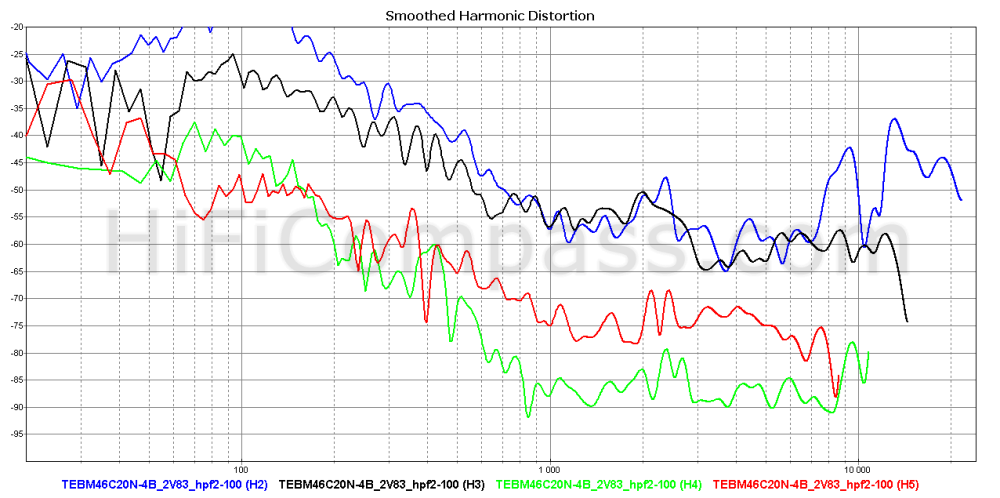
EDIT: here is the grap about harmonic distortions at 2.83v (315mm distance):
tebm46c20n-4b_315mm_2v83_hpf2-100.png
 

Dennis Murphy

Major Contributor
Technical Expert
Joined
Mar 17, 2020
Messages
1,071
Likes
4,547
You should click on the model; it directs you on the page with all the tests (drop down tabs that you have to click on too, not very common and weird way to design a web page).
The first driver measurements' page is here: TEBM46C20N-4.

EDIT: here is the grap about harmonic distortions at 2.83v (315mm distance):
tebm46c20n-4b_315mm_2v83_hpf2-100.png
Thanks very much. I guess that's consistent with the review measurements given that the mid is rolling off before the spike in distortion occurs.
 

zermak

Senior Member
Joined
Jun 2, 2019
Messages
373
Likes
251
Location
Italy
Thanks very much. I guess that's consistent with the review measurements given that the mid is rolling off before the spike in distortion occurs.
Yes, it is if you comfirm that's the mdirange driver you're using on the BMR project.
So like someone pointed out before the problem here is this particolar ribbon failing at around 3kHz.
If I may ask; have you avoided domes in this design because of their orizontal dispertion issues without a waveguide?
 

Dennis Murphy

Major Contributor
Technical Expert
Joined
Mar 17, 2020
Messages
1,071
Likes
4,547
Yes, it is if you comfirm that's the mdirange driver you're using on the BMR project.
So like someone pointed out before the problem here is this particolar ribbon failing at around 3kHz.
If I may ask; have you avoided domes in this design because of their orizontal dispertion issues without a waveguide?

I've done a number of designs for Jim Salk using dome tweets, and they would do very well on Spin tests without a wave guide. Wave guides are pretty much off my list of design approaches. I just prefer broader dispersion and the different character of the RAAL ribbons. Someone was asking why I just didn't use a 3/4" dome in the BMR, and the answer is the RAAL has broader dispersion--its radiating surface is half that of, say, the 0W1 and it doesn't have the same sssssssssssssssss quality that characterizes domes. ( I won't go into that last point here, but I've posted on it many times. I think it has something to do with the wave launch of a dome vs a ribbon.)
 

muad

Senior Member
Joined
Jun 8, 2019
Messages
420
Likes
481
Just to clarify, I don't think the RAAL is bright, I just felt the BMR as a whole was a bit bright in my small room, I wish I had a larger room to test the theory that it's related to the close sidewall reflections but I didn't. I tried the Mini Phil's before the BMR and felt they were a tad laid back so I don't believe it's related to the tweeter, the culprit to me seems to be in the range of the BMR midrange and the 1-3k range do seem very strong in this speaker. I never heard anything objectionable in either speaker that sounded like distortion but I also never listen anywhere close to the levels the distortion measurements are taken.
You're not alone in this. I found the speaker bright over all as well and they were being used in a large room with plenty of hard bare surfaces . It was especially noticable with older recordings, the Beatles, rolling stones etc. With good recordings it sounded incredible. It did things with the sound stage I've never heard before or since. The clarity was next level and voices were incredibly believable. I just couldn't use them with sub par recordings.
 

overg

Member
Joined
Jul 19, 2020
Messages
8
Likes
19
You're not alone in this. I found the speaker bright over all as well and they were being used in a large room with plenty of hard bare surfaces . It was especially noticable with older recordings, the Beatles, rolling stones etc. With good recordings it sounded incredible. It did things with the sound stage I've never heard before or since. The clarity was next level and voices were incredibly believable. I just couldn't use them with sub par recordings.


I'll jump on board with the notion that these certainly reveal recording flaws. Nothing more disappointing than loading up a great song on BMRs only to be met with a big fat "meh" of production. But I have a hard time blaming the speakers for that.

Erin, one interesting thing I noticed about your listening tests was that you had the speakers relatively close together (compared to your listening position) and towed in. You complimented the wide soundstage, but I wonder if pulling the speakers a bit farther apart and/or pointing them straight ahead would improve it even further. It's certainly possible it would just blur the soundstage or obliterate imaging, but might be worth a try.
 

R Swerdlow

Member
Joined
Jun 9, 2020
Messages
74
Likes
114
You're not alone in this. I found the speaker bright over all as well and they were being used in a large room with plenty of hard bare surfaces. It was especially noticable with older recordings, the Beatles, rolling stones etc. With good recordings it sounded incredible. It did things with the sound stage I've never heard before or since. The clarity was next level and voices were incredibly believable. I just couldn't use them with sub par recordings.
Is the BMR speaker the first of Dennis's designs that you've heard? Or have you heard a number of them? When I first heard one, I also thought it sounded somewhat bright. But that was easily explained, as what I was used to hearing was the opposite of bright sounding. I was quite used to that, especially with older recordings, such as the Beatles or Rolling Stones, as I often heard them over older speakers with poor sounding mid-range and treble. Some poorly recorded or mastered older recordings are unlistenable on some of Dennis's designs. For example, any of Creedence Clearwater Revival's earlier records. (That record producer should be shot.)

Your description above is similar to my own experience with a number of different speakers designed by Dennis. This includes 2-ways and 3-ways, and speakers with a variety of dome or ribbon tweeters. They all do do things with the sound stage and imaging that I'd never previously heard. In that aspect, I'd say the BMR speaker is among the best, if not the best of Dennis's designs. Dennis knows how to cross two drivers with each other so that there is little or no response dip around the crossover frequency, and within one octave of the crossover frequency, the two drivers are mostly in phase with each other. There's no "hole in the middle" to their sound, hence the initial impression that they sound bright. I would now say they are neutral sounding, and many other speakers I've known in the past, sound dull in comparison.

In my limited experience with two MTM designs of Dennis's, the Salk SongTower (with Hiquphon OW2 ¾" dome tweeter) and the Salk Veracity ST (with RAAL 70-20 ribbon tweeter), the Veracity ST actually does a better job with older poorly recorded music. But both of those MTMs are 2-way speakers and have crossover frequencies in the range of 2.5 kHz, much lower than the mid-to-tweeter crossover frequency in the BMR.
 
Last edited:

napilopez

Major Contributor
Forum Donor
Joined
Oct 17, 2018
Messages
2,146
Likes
8,718
Location
NYC
It seems weird to me that people are picking on distortion. Or at least without acknowledging the reason the compromise is made. We know what the research says about the audibility of distortions, let alone the question of what distortion counts as 'bad.'

There's been an added interest in distortion here of late. I love seeing the measurements, but always with a *huge* grain of salt on the audibility. I'm already a bit skeptical that it can affect Amir's impressions as much as he says(no offense, I'm just not convinced yet) but at least he has extensive, specialized training in that. If he can, it's because he's an outlier, which isn't very useful for the rest of us.

Don't go "you can't criticize if you don't do better", it's childish. Anyway, I completely agree with the two main concerns: distorsion is way too high in the important band (I'd say 300-3000 Hz) and ribbons like these are nothing but expensive gizmos, when you can get a similarly wide dispersion with a 3/4" dome tweeter with no real drawback.

For example, I found the Scanspeak R2004/602000 (or D) or Tymphany NE19VTS-04, while looking around a bit:
https://www.scan-speak.dk/product/d2004-602000/
index.php

https://www.scan-speak.dk/product/r2004-602000/
index.php

https://www.tymphany.com/transducers/ne19vts-04/
index.php

While I get the theoretical concerns from an optimization standpoint, and that in theory a very small tweeter might be able to match the RAAL's wide directivity, I've yet to see anyone point to a commercial design with similarly wide dispersion to the BMRs at near the price. If you can find a finished monopole speaker that has similarly wide dispersion and isn't using a ribbon or esoteric design/price, I'd love to see it. This is exactly what my preferences tend towards so I am constantly on the lookout. There are very, very few.

In any case, I'm not sure why you shared the drivers above. None of those really come close to the in-cabinet directivity performance of the BMRs. I haven't seen tweeter-only measurements for the specific RAAL in the BMR, so I'm not totally sure how the translation from raw tweeter to finished cabinet goes, but the data shared does not really compete at all The first driver is down by 5dB at 10kHz, the second by 7db at just 45 degrees off axis. That's very normal performance. By comparison, the BMRs are down about 2-3dB at the same point.

The third is a little better, down about 6dB at 60 degrees. But the BMR is again only down about 2dB. Out to 70 degrees, the speaker doesn't drop more than 5dB at any point from 2khz to 10khz, where it seems most of the soundstage size information happens. That is remarkable.

I'd wager that even a 1-2dB difference in off axis SPL is far more audible and --if you like wide directivity -- pejorative than an extra percent or two of distortion.

I also think there's a potential benefit to the ribbon's narrow vertical directivity; I have concerns that wider vertical directivity could exacerbate lobing and therefore timbral coloration. I also think the narrower vertical directivity might help make this speaker not sound too bright.

Like every speaker, the BMR has its flaws, but its directivity performance is quite rare. As Dennis said earlier, the distortion is in part due to the lack of a waveguide/horn loading in order to maximize directivity width. Imo that's a worthy trade-off. Speakers that minimize distortion as much as possible are easy to find and have questionable audible benefits.

Disclaimer: Never heard a ribbon speaker in my life. Just pointing out what I can see in the data.
 
Last edited:

ctrl

Major Contributor
Forum Donor
Joined
Jan 24, 2020
Messages
1,633
Likes
6,241
Location
.de, DE, DEU
Just to clarify, I don't think the RAAL is bright, I just felt the BMR as a whole was a bit bright in my small room, I wish I had a larger room to test the theory that it's related to the close sidewall reflections but I didn't.
I would also suspect that to be the cause.
Assuming the lateral reflections in the 60° range and looking at the normalized frequency response, the axis frequency response between 2-4kHz should be massively attenuated, which has been done partially, but also the 4-8kHz range should be attenuated - at least at a small lateral distance.

Because the midrange and tweeter radiate without any wave guide, the interaction with the loudspeaker baffle is particularly pronounced.

1595194167562.png
 

bigjacko

Addicted to Fun and Learning
Joined
Sep 18, 2019
Messages
723
Likes
360
Because the midrange and tweeter radiate without any wave guide, the interaction with the loudspeaker baffle is particularly pronounced.
Do you mean baffle diffraction? I thoguht baffle diffraction is only one frequency interference between the sound of driver and sound from the baffle edge, so should be a narrow peak or dip? The horizontal dispersion problem around 2.5k to 3.5k Hz might be the driver was not playing comfortably at there, indicated by distortion. But in the end the only problem is just on axis and 10 degree, if no toe in the dispersion is excellent and should be praised.
 
OP
hardisj

hardisj

Major Contributor
Reviewer
Joined
Jul 18, 2019
Messages
2,907
Likes
13,916
Location
North Alabama
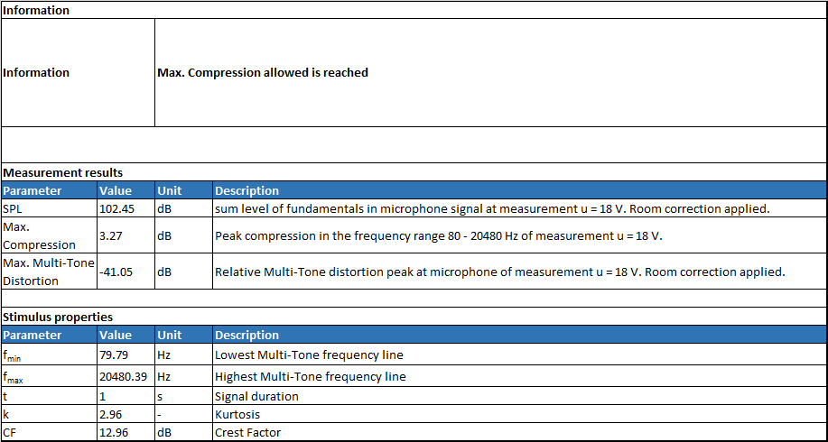
I just updated my site with the following Max SPL testing. Read the description and watch the video if you want to understand what is going on here.
I'll jump on board with the notion that these certainly reveal recording flaws. Nothing more disappointing than loading up a great song on BMRs only to be met with a big fat "meh" of production. But I have a hard time blaming the speakers for that.

Erin, one interesting thing I noticed about your listening tests was that you had the speakers relatively close together (compared to your listening position) and towed in. You complimented the wide soundstage, but I wonder if pulling the speakers a bit farther apart and/or pointing them straight ahead would improve it even further. It's certainly possible it would just blur the soundstage or obliterate imaging, but might be worth a try.

I did test them firing straight in to the room but the wide horizontal dispersion didn't seem to make a noticeable difference. Of course, these have the same directivity out to 60+ degrees, so...
 
OP
hardisj

hardisj

Major Contributor
Reviewer
Joined
Jul 18, 2019
Messages
2,907
Likes
13,916
Location
North Alabama
I just updated my site with the following Max SPL testing. Read the description and watch the video if you want to understand what is going on here.

Maximum Long Term SPL:
The below data provides the metrics for how Maximum Long Term SPL is determined. This measurement follows the IEC 60268-21 Long Term SPL protocol, per Klippel’s template, as such:

  • Rated maximum sound pressure according IEC 60268-21 §18.4
  • Using broadband multi-tone stimulus according §8.4
  • Stimulus time = 60 s Excitation time + Preloops according §18.4.1
Each voltage test is 1 minute long (hence, the “Long Term” nomenclature).

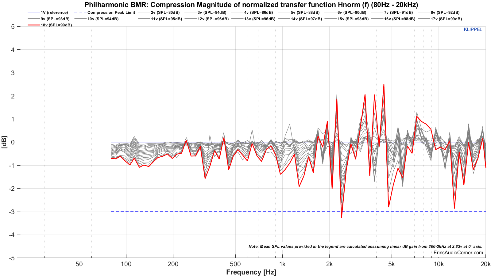
The thresholds to determine the maximum SPL are:

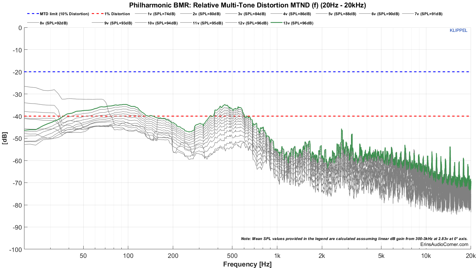
  • -20dB Distortion relative to the fundamental
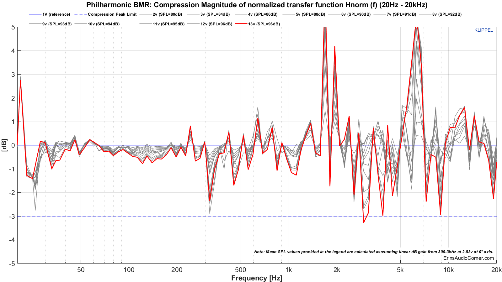
  • -3dB compression relative to the reference (1V) measurement

When the speaker has reached either or both of the above thresholds, the test is terminated and the SPL of the last test is the maximum SPL. In the below results I provide the summarized table as well as the data showing how/why this SPL was deemed to be the maximum.


This measurement is conducted twice:

  • First with a 20Hz to 20kHz multitone signal
  • Second with a limited 80Hz to 20kHz signal
The reason for the two measurements is because it is unfair to expect a small bookshelf speaker to extend low in frequency. Applying both will provide a good idea of the limitations if you were to want to run a speaker full range vs using one with a typical 80Hz HPF. And you will have a way to compare various speakers’ SPL limitations with each other. However, note: the 80Hz signal is a “brick wall” and does not emulate a typical 80Hz HPF slope of 24dB/octave. But… it’s close enough.

You can watch a demonstration of this testing via my YouTube channel:


Test 1: 20Hz to 20kHz

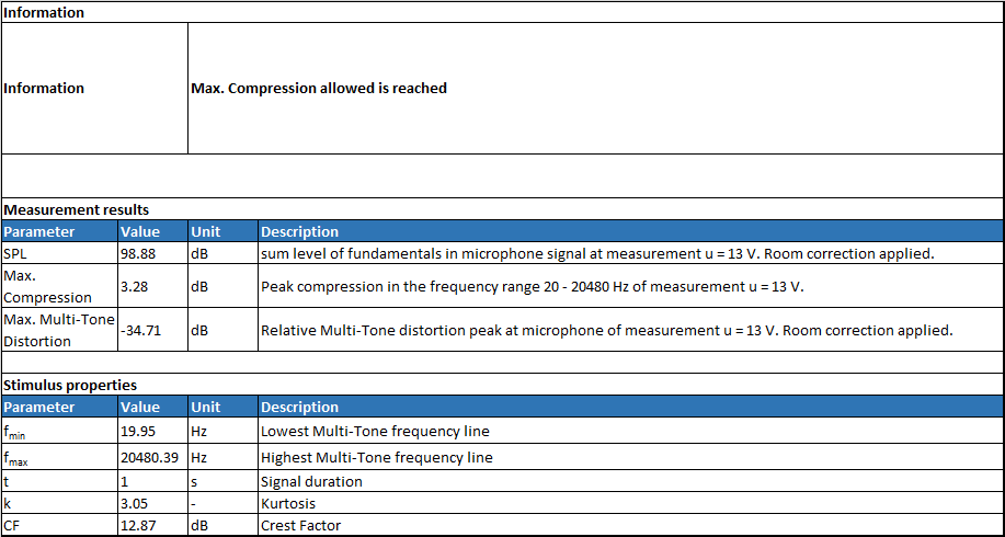
Table Results:
maxspl_table_20.png


Multitone compression testing. The red line shows the final measurement where either distortion and/or compression failed. The voltage just before this is used to help determine the maximum SPL.

Philharmonic%20BMR_MTON_Compression%2020.png


Multitone distortion testing. The dashed blue line represents the -20dB (10% distortion) threshold for failure. The dashed red line is for reference and shows the 1% distortion mark (but has no bearing on pass/fail). The green line shows the final measurement where either distortion and/or compression failed. The voltage just before this is used to help determine the maximum SPL.

Philharmonic%20BMR_MTON_Distortion%2020.png


Test 2: 80Hz to 20kHz

Table Results:
maxspl_table_80.png


Multitone compression testing. The red line shows the final measurement where either distortion and/or compression failed. The voltage just before this is used to help determine the maximum SPL.

Philharmonic%20BMR_MTON_Compression%2080.png


Multitone distortion testing. The dashed blue line represents the -20dB (10% distortion) threshold for failure. The dashed red line is for reference and shows the 1% distortion mark (but has no bearing on pass/fail). The green line shows the final measurement where either distortion and/or compression failed. The voltage just before this is used to help determine the maximum SPL.

1595215314528.png


The above data can be summed up by looking at the tables above but is provided here again:

  • Max SPL for 20Hz to 20kHz is approximately 99dB @ 1 meter. The compression threshold was exceeded above this SPL.
  • Max SPL for 80Hz to 20kHz is approximately 102dB @ 1 meter. The compression threshold was exceeded above this SPL.
 
Last edited:
OP
hardisj

hardisj

Major Contributor
Reviewer
Joined
Jul 18, 2019
Messages
2,907
Likes
13,916
Location
North Alabama
If you have a keen eye you will notice the SPL I provide in the legend doesn't match the Max SPL. That's because:
1) The last SPL in the legend is the test that failed. As I said, you'll have to use the SPL from the voltage run before the last; that's where the max SPL is pulled.
2) I round in my legend. So I may be off by a dB or so, depending on the rounding.


To the inevitable naysayers: I seriously hope you guys understand the value of accurate data like this. It's no walk in the park to provide this. I have literally spent the entire weekend testing, studying, learning and finally re-testing again. If you have gripes, take it up with the IEC and the guys at Klippel who made the template I used explicitly. Besides all of this, name one other person doing this test and providing videos of how they are conducted. So, don't start throwing rocks if you don't like this. I'm not re-doing a dang thing here.


And now, I'm gonna take a much needed break. :D
 

ctrl

Major Contributor
Forum Donor
Joined
Jan 24, 2020
Messages
1,633
Likes
6,241
Location
.de, DE, DEU
Here is a small analysis why the radiation of the loudspeaker looks like what it looks like.

I have simulated a very simple model of the loudspeaker. For this purpose the ideally behaving driver cones were simply placed flat on the baffle, the dimensions of the drivers should be roughly correct - the ribbon tweeter is 1cm too short (had measured wrong), but this should only have a vertical effect.
To save computing time, a depth of only 20cm was set for the loudspeaker cabinet - thus the simulation to low frequencies (<600-800Hz) is not quite correct. At about 10Khz the simulation is also no longer reliable (again to save computing time).

1595202962069.png


First we look at the horizontal normalized frequency response of the midrange driver - which in the Phil BMR has its crossover frequency at 3kHz.
It is clearly to see that the midrange driver radiates somewhat narrower between 1-2kHz and in the range 2-4kHz it radiates much wider due to the edge diffraction (interaction with the baffle) - related to the normalized 0° frequency response.
1595203661092.png


If we only look at the midrange driver, a crossover frequency of 2kHz would be appropriate to avoid broadening in the radiation. But of course we also have to look at the radiation pattern of the tweeter - again normalized to the 0° frequency response:
1595204898982.png


You can immediately see that the edge diffraction is more dramatic for the tweeter. Even between 5-8kHz the edge diffraction is still clearly noticeable.
So of course it makes no sense to choose the crossover frequency as low as possible e. g. 2kHz (even if the ribbon tweeter would be able to do so), because otherwise the effect of edge diffraction would be even more pronounced.

Let's put it all together and look at what the simulation predicts at a crossover frequency of 3kHz with LR4:
1595205849336.png


This results for the horizontal radiation of the loudspeaker normalized to 0°:
1595206009215.png


It is easy to see, for example, that the 60° frequency response increases steadily in sound pressure from 1.5kHz onwards and that from 2.3kHz onwards it has a higher sound pressure than the midrange.
In order that the loudspeaker does not sound too bright at a short distance from a side wall, the axis frequency response would have to be corrected accordingly to compensate for the increase at the different angles.


But in the end the only problem is just on axis and 10 degree, if no toe in the dispersion is excellent and should be praised.
I don't think I made myself clear.

The dispersion is very even, but at an angle the sound pressure of the tweeter is up to 70° clearly above that of the midrange, which could lead to the said bright sound at a small distance to a side wall, since the LW and axis frequency response are rather flat.

In large rooms and at normal volume this tuning ensures a high level of detail - it's always a compromise.
 

bigjacko

Addicted to Fun and Learning
Joined
Sep 18, 2019
Messages
723
Likes
360
@ctrl Wow, very nice work, thank you for doing this. Now I see why the 3k Hz and 6 to 7k Hz are dffraction. Your simulation is very close to the real speaker measured. Do you know why at around 600 Hz the dispersion start to get narrower? Why is the combined response at 3k Hz is actually a small dip rather than a peak? Also may I ask what is the software you used?
 

Dennis Murphy

Major Contributor
Technical Expert
Joined
Mar 17, 2020
Messages
1,071
Likes
4,547
Thanks for all of the great documentation. I don't have any gripes about the distortion test. As soon as I found this forum I knew somebody was going to do a Klippel on the BMR, and I knew distortion was going to be the central issue. At this point, I don't really know where virtue lies. This is just another unsettled issue that makes audio, and audio design so interesting. All I will say is that I can't see any way to reduce the tweeter distortion substantially without lowering the overall quality of the speaker. If there were such a solution, and even if it involved added cost, I would simply offer an alternative upgraded version at a higher price. I would note, however, that current and future BMR's use a different "x" version of the 64-10 tweeter that has a reworked chamber to allow a lower crossover point, or to lower distortion at the same crossover point. I would say the reduction is on the order of .5 percentage points at high output, but I'll have to do another measurement to confirm that. I do have a few other observations and a question or two for hardisj.

1) The other area where the BMR seems to fall a little short is in the predicted in-room response. Part of that is no doubt due to the unusually wide treble dispersion, but part also derives from the positioning point of the "optimal" slope, which starts where the BMR midbass response appears to ramp down 2-3 dB. I've never seen that response profile in any other test of the BMR, including the NRC test, the Audioholics Spin test, or my nearfield measurements. It certainly wasn't designed in. So this is very puzzling to me.

2) The little dip in the 3 kHz region is not a diffraction effect or a crossover issue. I deliberately built that in to offset a diffraction bump that develops off axis in that region. I know--I know--if I had JUST used a wave guide I wouldn't have had that problem. And I wouldn't have had as good a speaker either. It's interesting that someone posted about the possible meritorious effects of using a curved cabinet that bowed out on the sides and would therefore in effect create a much wider round over and reduced off-axis diffraction. We ordered a test cabinet with that shape a few weeks ago, and it just arrived yesterday. I took some measurements using the current BMR crossover, and there were absolutely no peaks or dips off axis. We'll offer that version as an option early next year.

3) Question for hardisj. I'm sure this has been explained somewhere sometime, but I'm still very confused about how the nearfield Klippel measurements get translated into one meter or far field response. I know there's lots of math involved and I'm not expecting you to go into that. But are the curves you're showing what Klippel is predicting the one-meter response will be? And can you ask Klippel to give you the predicted response at virtually any distance, like the 3-meter distance I optimized the BMR for? Anyhow, thanks very much for your contribution. I'll ask Santa to stick a Klippel machine in my Xmas stocking. Ho Ho.
 
Top Bottom