• WANTED: Happy members who like to discuss audio and other topics related to our interest. Desire to learn and share knowledge of science required. There are many reviews of audio hardware and expert members to help answer your questions. Click here to have your audio equipment measured for free!

KEF LSX Teardown and Repair

Great repair review!

I have a pair of KEF LSX which has a power issue on the secondary speaker. Whenever I plug in the secondary speaker, the relay keeps ticking. My guess that it is trying to turn on but due to a fault somewhere on the PSU board, it switches off. I measured some voltages and found out that the DC output of the rectifier seems very imbalanced. On the (+) side, the DC output was 133 Vdc and (-) side was 28 Vdc. I compared the voltage values with the primary speaker PSU and on the (+) and (-) side, it was both 133 Vdc.

Any help will be greatly appreciated as I feel that I am at a deadend. Thank you in advance!
 
Well, it is not a lot of information, I would need to know more precisely what are you measuring, but at first sight it looks like the primary rectifier is working half-wave. I would suggest that you check the 4 diodes of the rectifier with a multi-meter (diode test function, with no mains voltage), likely one of the diodes is open. If it is the case then replace the rectifier, redo the voltage measurement and if it is correct the loudspeaker should work again, otherwise let me know. In that case if you can, it would help if you post a photograph of the PSU board indicating where are you doing the voltage measurements, such that I can help more.
 
Well, it is not a lot of information, I would need to know more precisely what are you measuring, but at first sight it looks like the primary rectifier is working half-wave. I would suggest that you check the 4 diodes of the rectifier with a multi-meter (diode test function, with no mains voltage), likely one of the diodes is open. If it is the case then replace the rectifier, redo the voltage measurement and if it is correct the loudspeaker should work again, otherwise let me know. In that case if you can, it would help if you post a photograph of the PSU board indicating where are you doing the voltage measurements, such that I can help more.
I tested the rectifier in diode mode in this order:
M (Multimeter) & R (Rectifier)
1) M+ to R- & M- to R~ = 0.551V drop
2) Reverse = OL
3) M- to R+ & M+ to R~ = 0.562V drop
4) Reverse = OL
5) M+ to R- & M- to R+ = 0.966V drop

Below are the voltage measurements over the 2 220uF 250V capacitors after the Vishay GBU 4K rectifier. I realised that the DC voltage readings are different each time I turn on the speaker using the remote. At times, the voltage readings will rise as high as 300Vdc and sometimes it will stay at 130Vdc.

KEF LSC PSU.jpg
 
Ummm...Then I don't think there is a problem with the rectifier even if you didn't measure all 4 diodes. On the 220uF capacitors you should see 130-150V, not 280-300V, which is above the voltage rating of these capacitors. If voltage measurements are erratic it can be a lot of things, maybe also just measurement issues. I don't have much to recommend. Maybe you can still check the following:
- Is the stand-by power supply OK? Or will it sag when you turn on the speakers?
- Can you check the voltage on the capacitor on the primary side of the stand-by power supply? It is a 33uF/400V capacitor, and you should see about 130-150V if your mains voltage is 120V and 260-300V if it is 230V.
- Was the voltage measurement done while the relay was closed?
- Do you see at least the 30V supply voltage for the power amplifier on the secondary side?
If you don't find something obviously wrong with these checks, then I think that you should find somebody that can repair your PSU, it is difficult to do it in remote without having the PSU here.
 
Very interesting thread. I currently use the KEF X300A, which had some issues with the Master amp board. I fixed that and they play really well. Now my daughters KEF LSX are acting up. Same symptoms as shown here, amber/red LED. In my case, there is no damage to any of the caps or the choke. I replaced them anyway, but the issue persists. Very weird. I went over the board, front and back with my multimeter and microscope and cannot find anything unusual. Any idea what else could cause this?

I did try a firmware recovery, which worked fine, but did not resolve the issue.

Update: poor me, now my KEF LS50 Wireless are also dead…did have the time to check them yet. What’s wrong with KEF speakers?
 
Ummm...Then I don't think there is a problem with the rectifier even if you didn't measure all 4 diodes. On the 220uF capacitors you should see 130-150V, not 280-300V, which is above the voltage rating of these capacitors. If voltage measurements are erratic it can be a lot of things, maybe also just measurement issues. I don't have much to recommend. Maybe you can still check the following:
- Is the stand-by power supply OK? Or will it sag when you turn on the speakers?
- Can you check the voltage on the capacitor on the primary side of the stand-by power supply? It is a 33uF/400V capacitor, and you should see about 130-150V if your mains voltage is 120V and 260-300V if it is 230V.
- Was the voltage measurement done while the relay was closed?
- Do you see at least the 30V supply voltage for the power amplifier on the secondary side?
If you don't find something obviously wrong with these checks, then I think that you should find somebody that can repair your PSU, it is difficult to do it in remote without having the PSU here.
The voltage measurements are done with the relay open as it does not remain closed when I switch on the speakers.
Stand-by power supply on the primary side over the 33uF/400V capacitor is at 320V. My mains are 230V.

I have got some progress. I replaced the various electrolytic capacitors with Panasonic FK caps that I purchased from Element14 on the PSU except the 3300uF/50V capacitor across the 30V rail as I missed out on it when I was ordering the replacement caps. Now, the power supply is able to remain switched on but it stays on for a random amount of time. However, when the power supply switches off, there is a loud pop from the speakers and I assume that there's a power surge which cause the loud popping sound. When the speaker is able to be switched on, the voltage across the 2 220uF capacitors are between 130-160V so my guess that the primary circuit is fine and the problem might be on the secondary circuit.

I am determined to learn how to repair this power supply as I have got background repairing circuit boards but I never dared to touch a power supply before so pardon me if I am not clear on how to troubleshoot the power supply :oops:
 
Yep :) I have the LSXii and the LS60 and dual KC92’s .

But had a bunch of actives my Meridian system worked fine , my fostex still works. A pair of Adam’s broke for me .

It’s a bit all eggs in the same basket ? But I’m very fond of active speakers when they work .
 
The voltage measurements are done with the relay open as it does not remain closed when I switch on the speakers.
Stand-by power supply on the primary side over the 33uF/400V capacitor is at 320V. My mains are 230V.

I have got some progress. I replaced the various electrolytic capacitors with Panasonic FK caps that I purchased from Element14 on the PSU except the 3300uF/50V capacitor across the 30V rail as I missed out on it when I was ordering the replacement caps. Now, the power supply is able to remain switched on but it stays on for a random amount of time. However, when the power supply switches off, there is a loud pop from the speakers and I assume that there's a power surge which cause the loud popping sound. When the speaker is able to be switched on, the voltage across the 2 220uF capacitors are between 130-160V so my guess that the primary circuit is fine and the problem might be on the secondary circuit.

I am determined to learn how to repair this power supply as I have got background repairing circuit boards but I never dared to touch a power supply before so pardon me if I am not clear on how to troubleshoot the power supply :oops:
You should not replace components at random before finding the root cause of the failure. The risk is that the root cause gets hidden, or, worse, you add a new problem that will need to be found.
The loud pop suggests that now there may be an issue (also) with the power amplifier. Did the loudspeaker pop at power off also before you replaced the capacitors? Is there DC on the loudspeaker's voice coil when the amplifier is powered up? If yes it could be that there is indeed a problem with the amplifier, and maybe the PSU was just reacting by opening the relay thus cutting off the main power supply. Who knows!
 
Imo if you diy repair , you should be very skilled and have proper equipment ( and safety training/experience if you handle 230VAC or 120VAC ) .

if you not that skilled you migth treat it as a learning experience and the speaker is a writeoff and its a bonus if it comes alive again , but don't skimp on safety !!

For a long term quality solution whole board replacement is usually the best ?

My own experience is from repairing variable speed drives ( frequency converters and DC-drives ) and controll systems . On circuit board repairs is another level and skill set I've done some of it in the 90's but rarely .

Thanks to @FraPia-62 for the great info . Hopefully someone else splits open version 2 of the LSX . I have no problem with an arm based soc ( massive experience from telecom should ensure reliability beyond audio ) But cheap capacitors is a concern to me ? they could be fit for pupose or just cheap who knows ?
But some caps where found to be under speced ??

Several KEF designers are on this forum btw , but they might not want to comment ( the are polite and friendly but media trained ).

Off topic .

PCB's can be designed and built by subcontractors and manufacturing farmed out to somewhere else.
There are possibly batch variations and sometimes component changes unknown to the original designers ? as someone just replaced an out of stock item with an "equivalent" :)
This happens to large industrial companies too ( ask me how i know ) QC is another skill set .
 
Very interesting thread!

Btw ... Is it just me to find the chassis’s photos a bit surprising, showing no markings or labels on them? That way it looks like some obscure no-name product.

1726560374070.png
 
Kef makes thier own drivers or have them made . Others buy directly from manufacturers or have some custom versions made of existing drivers, Kef drivers are truly unique to Kef .
 
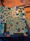
I also diverted my attention to the PSU, since replacing choke and caps did not resolve the issue.

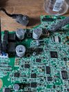
Using my thermal camera, I found that two 300kOhm resistors R816 and R817 get hot. They are sitting on both sides of the PCB directly opposite of each other, so I am not sure which one gets hot. Might be both. Will replace them and see.

Btw, that soldering job is from factory, not from my probes. Also U804 has some weird solder blobs.
Anyway, I checked all my doner boards, but have no 300kOhm resistor. I will check some other doner boards tomorrow, most likely will have to order resistors.

IMG_2426.jpeg
IMG_2425.jpeg
IMG_2428.jpeg
IMG_2429.jpeg
 
Hi,

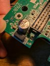
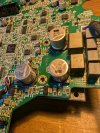
Finally, I had time to complete the repair. In addition to the main fixes, I replaced three of the large electrolytic capacitors with Panasonic EEV-FK1H331Q. However, the recommended 63V version wasn’t ideal, as the footprint turned out to be too large.

One of the smaller capacitors, a 470µF 6.3V, looked suspicious as well, so I swapped it out for a Nichicon UCD0J471MNL1GS.

Cracked capacitor C433 with a Murata GRM32DC72A475KE01L (4.7µF, 100V DC).

Ferrite bead L236 was replaced with a Murata BLM31PG391SN1L (100MHz, 390Ω)

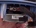
OK. Sources say it could be a KEF SP1777GA chassis, with serial-no. label somewhere on the magnet’s outer rim.
On my speaker label shows KEF SP1777EA
 

Attachments

  • PXL_20240918_153901632.jpg
    PXL_20240918_153901632.jpg
    311.1 KB · Views: 71
  • PXL_20240918_153831337.jpg
    PXL_20240918_153831337.jpg
    458.7 KB · Views: 62
  • PXL_20240918_153359443.jpg
    PXL_20240918_153359443.jpg
    468.7 KB · Views: 70
  • PXL_20240918_162717865.jpg
    PXL_20240918_162717865.jpg
    261.4 KB · Views: 62
  • PXL_20240918_153910803.jpg
    PXL_20240918_153910803.jpg
    453.3 KB · Views: 72
Hi,

Finally, I had time to complete the repair. In addition to the main fixes, I replaced three of the large electrolytic capacitors with Panasonic EEV-FK1H331Q. However, the recommended 63V version wasn’t ideal, as the footprint turned out to be too large.

One of the smaller capacitors, a 470µF 6.3V, looked suspicious as well, so I swapped it out for a Nichicon UCD0J471MNL1GS.

Cracked capacitor C433 with a Murata GRM32DC72A475KE01L (4.7µF, 100V DC).

Ferrite bead L236 was replaced with a Murata BLM31PG391SN1L (100MHz, 390Ω)


On my speaker label shows KEF SP1777EA
Looks good. I also have the Panasonic Caps on order. Should be in tomorrow.

Did you test the speakers? Did you have to do a recovery or did it work just fine after the repairs?
 
Looks good. I also have the Panasonic Caps on order. Should be in tomorrow.

Did you test the speakers? Did you have to do a recovery or did it work just fine after the repairs?
Hi,

Everything worked perfectly for me, and it's been running smoothly for a few hours now without any issues. No need to do a recovery in my case.

When replacing SMD capacitors, make sure to clean the pads thoroughly to remove any old solder. Also, be cautious with the heat—SMD components require a bit more heat because the PCB will absorb some of it. Just take your time, and ensure proper heat distribution to avoid damaging the pads or components. Remember, flux is your friend! It helps with solder flow, but make sure to clean it off afterward to prevent long-term damage.
 
  • Like
Reactions: MCH
Hi,

Everything worked perfectly for me, and it's been running smoothly for a few hours now without any issues. No need to do a recovery in my case.

When replacing SMD capacitors, make sure to clean the pads thoroughly to remove any old solder. Also, be cautious with the heat—SMD components require a bit more heat because the PCB will absorb some of it. Just take your time, and ensure proper heat distribution to avoid damaging the pads or components. Remember, flux is your friend! It helps with solder flow, but make sure to clean it off afterward to prevent long-term damage.
Thats awesome. Im glad it worked for you. I hope this will last for years.

Yeah, I definitely will he careful, I am more the “through-hole” solder guy but I have some good equipment. My issue is more my eyes, its all so tiny and i wish I had a microscope.

Just a question, I just did some more testing. I did replace most SMD caps, choke and zener diode, but the issue persisted. I then checked the PSU, but just now I also noticed R411 glowing when switching power. That resistor is right next to the zener diode and im sure its not supposed to glow like a christmas tree light.

Next week I will have some time to repair my Kef LS50 Wireless. Maybe I will also do a tear down.
 
Back
Top Bottom