• WANTED: Happy members who like to discuss audio and other topics related to our interest. Desire to learn and share knowledge of science required. There are many reviews of audio hardware and expert members to help answer your questions. Click here to have your audio equipment measured for free!

KEF LSX Teardown and Repair

Thats awesome. Im glad it worked for you. I hope this will last for years.

Yeah, I definitely will he careful, I am more the “through-hole” solder guy but I have some good equipment. My issue is more my eyes, its all so tiny and i wish I had a microscope.

Just a question, I just did some more testing. I did replace most SMD caps, choke and zener diode, but the issue persisted. I then checked the PSU, but just now I also noticed R411 glowing when switching power. That resistor is right next to the zener diode and im sure its not supposed to glow like a christmas tree light.

Next week I will have some time to repair my Kef LS50 Wireless. Maybe I will also do a tear down.
Hi,

If R411 is getting hot something is drawing to much current. I seen some comments that in worst cases Q211 might get damage as well. Can you check shortages between each pin?
Q211
 
Hi,

If R411 is getting hot something is drawing to much current. I seen some comments that in worst cases Q211 might get damage as well. Can you check shortages between each pin?
Q211
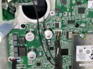
Funny enough, I read that as well and have already ordered some together with the Panasonic caps. I did measure R411 and its resistance is fine. I will replace Q211 tomorrow and see what happens. I did not remove Q211, so that could influence the result, but base and emitter results in OL in diode mode. Same with base and collector.
 
Im just wondering whether R411 on the board and R816/817 have the same root cause for getting hot. R816/817 seem to belong to the +3.65V line feeding to the board.
I have tested every cap and resistor around the Q211 area and nothing seems shorted. testing Q211 gives me reversed results, so basically it’s an NPN transistor, which gives me PNP results when testing.

Update: Just received the new transistor and took some measurements, getting 0.54 voltage drop, while the old one gives me OL. I replaced Q211, but the issue persists. R411 still gets hot, might be normal, who knows. One thing that bothers me is the LED blinking red in the middle of the PCB. Anyone knows what that indicates?

Another thing bothering me is that Q211 does NOT warm up. I know that these transistors can get rather hot during normal operation. That thing is dead cold and only R411 gets hot. I am puzzled.
 
Last edited:
Im just wondering whether R411 on the board and R816/817 have the same root cause for getting hot. R816/817 seem to belong to the +3.65V line feeding to the board.
I have tested every cap and resistor around the Q211 area and nothing seems shorted. testing Q211 gives me reversed results, so basically it’s an NPN transistor, which gives me PNP results when testing.

Update: Just received the new transistor and took some measurements, getting 0.54 voltage drop, while the old one gives me OL. I replaced Q211, but the issue persists. R411 still gets hot, might be normal, who knows. One thing that bothers me is the LED blinking red in the middle of the PCB. Anyone knows what that indicates?

Another thing bothering me is that Q211 does NOT warm up. I know that these transistors can get rather hot during normal operation. That thing is dead cold and only R411 gets hot. I am puzzled.
A blinking red LED on the PCB is part of normal operation. During my initial test, the LED was blinking as well. If you don’t have any shorts, I’d recommend going ahead and testing whether you can power on and control the device.

For now, leave the speaker disconnected and focus on setting up the mobile app and assigning the device an IP address. If there's an issue, the front LED should indicate protection mode.
 

Attachments

  • PXL_20240726_1853057162-ezgif.com-optimize.gif
    PXL_20240726_1853057162-ezgif.com-optimize.gif
    3.1 MB · Views: 27
Thank you for your support, much appreciated.

I can power the speaker on and after a reset, I can pair it with the app, as long as the LED is orange/white. After adding the speakers to the app, I can hear a Relais clicking and the LED flashes orange/red immediately. I can find the speakers on my iPhone and play music, but no sound from the master. When powering off with the remote, the slave plays the chime, nothing from the master.

Symptoms remain the same, so the slave does play sound, but it reduces volume on its own until 0. Any idea why it reduces volume?

I just tried a firmware recovery, but that did not do anything.

This afternoon, I also swapped the PSU from the slave to the master, just to remove that from the potential root causes. So far, nothing worked.

Picture of my solder job, all connections seem fine.
 

Attachments

  • IMG_0683.jpeg
    IMG_0683.jpeg
    448.2 KB · Views: 38
It sounds like the protection circuit is activating once the amplifier section powers up. I’d recommend measuring the voltage at the speaker output to check if overvoltage is the issue. Without the schematics, troubleshooting could be challenging, but this is a good starting point.

Reducing volume on slave might be part of protection sequence.
I followed your advice and measured the voltage at the speaker output. Right after switching on the voltage jumps to 12.2V and immediately drops down to 2.3V and then down to 0.2V-0.0V. This happens on both channels. For a few seconds, I can see the voltage bouncing a bit, mainly downward.


update: I just got myself a new multimeter, since my old one was a $10 unit. When measuring Z203 and C435 they beep on both sides now. Using the old multimeter they dont. Seems they are both shorted to ground or the cap causes the zener to beep.
 
Last edited:
Glad to hear you got a better multimeter! The Zener might not be the issue. I’d suggest checking the surrounding capacitors again—there could be a short somewhere. Without a thermal camera, pinpointing the problem might be tricky, but you can use IPA (isopropyl alcohol) to identify any components heating up.

I’d start by inspecting around R411 and the capacitors you replaced. You can also remove the diode and test it outside the circuit, but remember to note its orientation before reinstalling it. It’s worth looking under a microscope or magnifying glass to see if any other capacitors look suspicious.
 
I think I found the issue. As soon as I removed the zener diode, the short on C435 disappeared. Might be that I used too low value diode as replacement. Under the microscope the original diode (which i kept, just in case) says „220“ on it. if thats the voltage rating, its higher than anything i have. I have 39V, which will not work.

I might want to check the old one to see whether it has a fault. But i dont like using parts I have already removed…
 
So I took the chance and put a 39V zener diode in and the short in Z203 and C435 is gone. I also replaced C435 just to be sure. The original zener diode seems faulty when measuring. However, the issue still persists. So I took some measurements while powered.

Seems I get 30V now around R411, but 0V from D205 on. The 3.3V seems fine, which seems for the link module. The choke also does not have any voltage, C434 has 30V. I don’t know much about chokes, so I am not sure whether that is expected. I did order some more parts which will arrive today. Not giving up here. Next I will try to understand whether 30V is the correct voltage and if C439 is supposed to have 30V as well. Seems odd that there is a 0V area around D205. My thermal camera does not pick anything up here.

IMG_0683.jpeg
 
So I took the chance and put a 39V zener diode in and the short in Z203 and C435 is gone. I also replaced C435 just to be sure. The original zener diode seems faulty when measuring. However, the issue still persists. So I took some measurements while powered.

Seems I get 30V now around R411, but 0V from D205 on. The 3.3V seems fine, which seems for the link module. The choke also does not have any voltage, C434 has 30V. I don’t know much about chokes, so I am not sure whether that is expected. I did order some more parts which will arrive today. Not giving up here. Next I will try to understand whether 30V is the correct voltage and if C439 is supposed to have 30V as well. Seems odd that there is a 0V area around D205. My thermal camera does not pick anything up here.

View attachment 393723
I have absolutely no idea so take my comments for what they are. I would expect something like 12V at the output of one of those regulators, i.e. Q211 you encircle the whole part as 30V. Is that the voltage at the output pins too? Doesn't seem right. The big electrolytic in the 30V zone must be in the vdd rail for the amp chip so it is likely right. The reason for the 0V at the choke in the corner could it be that it is connecting two grounds? Like ground plane to chasis or something like that? (Again, just guessing)
I would bet 5 euros (not more) that if you really have 40V at the output of that LDO you might have damaged the chip amp...
Thanks for your answer. Here in Germany we have an expression „kaputt repariert“. Easy to understand, I guess..haha.

Anyway, from the back of the PSU PCB I can see that 30V is indeed a voltage supplied, but I did not trace where to. I think I will remove all SMDs in the corner once more, clean everything up and start fresh. Unfortunately, a little bit of the PCB mask came off at C434 and i cannot find my solder mask. gotta get that fixed first.

It’s quite fun to work on this. At least I can get my SMD solder skills improved. I usually only repair vintage HIFI, mainly Luxman and Sony, which is mostly through hole.
 
Hi,

In my case I had to do a bit of cleaning as PCB charcoaled. Make sure you clean as well and check if you have continuity on tracks that does follow components as they might get damaged.

Wish you luck, hope you find the problem.
 
Hi,

In my case I had to do a bit of cleaning as PCB charcoaled. Make sure you clean as well and check if you have continuity on tracks that does follow components as they might get damaged.

Wish you luck, hope you find the problem.
Thank you for the advice. I just checked the traces and they do seem fine. I also traced the current path to go to the DSP from L236. I hope I did not fry that.

I found that rectifier D205 and D207 are open in both directions, which seems to indicate a short. Also when I test C467 and C471 the positive is shorted to ground. I took C467 off the board and confirmed that positive is shorted to ground. Still digging around a bit.

So, if I am correct, the voltage comes in through L236 into Q211, there it passes through the collector into R411 with Z203 and C436 as protection circuit. From R411 back into the Base of Q211 out the emitter to D205. I remember some people bridging L236 with a wire, which worked fine. But that would also mean that the 30V coming through L236 is expected? If not, the short might be somewhere completely different. My thermal cam doesn’t give me any clue.

Btw Q211 is dead, its the 2nd now that died.
 
Last edited:
So I have spent the evening rebuilding that entire corner. I have taken my time and great care, working mostly with hot air. I also masked all the tiny scratches. I replaced all caps in that area and installed a new 20V zener diode.

I tried to spend some time looking at the circuitry with all components removed from the board. I also powered the board without components to take some measurements. all in all, the only concern i have now are the 2 rectifier D205 and D207, which are open both ways. Anyone has any advice on these?
IMG_2449.jpeg
 
Funny how I missed the schematics posted here earlier. Makes all much clearer and also aligns with my findings described above. So, 30V coming in and passing through Q211, Z205 and then through the voltage regulator U20, which puts out 12V to C440. I have not measured yet, but U20 is rated for 26V max input voltage. Not sure what happens if it receives 30V for a longer time. I would have to measure voltage at its input to see what it really gets from Q211.

For sure, voltage at C440 was 0.0V last time I checked. So, I probably will replace Z205 first and C437 and C438 as well, just in case. Hope this works. Until those diodes arrive, I will see how to open my LS50 Wireless and create a new post for those.
 
Hey there! My used KEF LSX just arrived and after 30 min of delivering great sound the main now shows the infamous red/orange blinking led. It persists through resets and shows the behaviour described in this thread. I'm very sad that this seems to be a real hardware issue but seeing this currently active forum thread gives me a shimmer of hope - with my electrical engineering background I'd be motivated to try repairing the speakers. So in the coming days I'll also perform some measurements on the PCB, I'll keep you updated and am looking forward to cooperating :)
 
Hey there! My used KEF LSX just arrived and after 30 min of delivering great sound the main now shows the infamous red/orange blinking led. It persists through resets and shows the behaviour described in this thread. I'm very sad that this seems to be a real hardware issue but seeing this currently active forum thread gives me a shimmer of hope - with my electrical engineering background I'd be motivated to try repairing the speakers. So in the coming days I'll also perform some measurements on the PCB, I'll keep you updated and am looking forward to cooperating :)
Thats really sad to hear. You will find the schematics on page 2. From what I saw around the next, most issues came from L236 and the capacitors around it. Just mine are a pain in the butt. But, I think I am close to fixing them. Just waiting for some diodes to arrive.

Good luck with the repair. I think most repairs are successful rather quickly.
 
Alright I guess it's not hard to see that L236 is at fault for me, too. Thanks a lot guys (and especially @FraPia-62!), without you I wouldn't have been able to find this :) I'll order the spare parts (probably also C434 next to 433 since it was quite in the blast zone), do my best to fix it and report back!
IMG_0290.jpeg

Good luck also to @Tokyoskies, I'm sure you'll fix it!
 
Back
Top Bottom