OK, here are a few ideas. You get what you pay for, so don't sue me ;-)Far out!
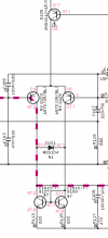
To adjust the DC offset, we want to inject a +/- adjustable current into the front end. The top of resistor R119 is a good spot, because a voltage developed there will alter the bias on Q103 through resistor R109. A simple way is to connect a potentiometer between the +/-15V supplies in the preamp, and then have a 100k resistor to limit the current to the top of R119. This should produce a swing of ~+/-100mV on the output. Reduce the 100k resistor if you want more, increase it if you want less. Excuse my lame MS Paint sketches.
A slightly more elaborate approach adds RC filters on either side of the potentiometer, which divides the voltage by 1/3, so the output resistor goes to 33k:
For the output bias, Q117 forms the bias circuit known as a Vbe multiplier. The collector to emitter voltage of Q117 will equal its base to emitter voltage Vbe times a divider ratio determined by R129, R133, R175, and R131: Vce = (R129 + R133 || R175 + R131)/(R133||R175+R131) * Vbe. The Vce of Q117 sets the bias across the output devices because it determines the voltage difference between the bases of Q119C and Q119A. We can adjust this bias by tampering with this resistor divider. I propose removing R133 and inserting a 1K trimpot in its place, as shown. The original divider has a ratio of 3.67. The modified circuit has a variable ratio from 3.20 to 4.29.
The failure mode of a potentiometer is the wiper going open, so if that happens we want to reduce bias and suffer more distortion rather than increasing bias and risking thermal failure. If the wiper goes open the ratio goes to its smallest value and reduces the bias on the output, so it fails safely. Likewise the failure mode of the offset circuits is you get no offset control and resort to factory settings.