• WANTED: Happy members who like to discuss audio and other topics related to our interest. Desire to learn and share knowledge of science required. There are many reviews of audio hardware and expert members to help answer your questions. Click here to have your audio equipment measured for free!

[FIXED] Yamaha A-S700 intermittent power-on failure (and eventually full failure)

catch22

Member
Forum Donor
Joined
Feb 10, 2024
Messages
68
Likes
29
Location
Ireland
[ SOLVED ] Yamaha A-S700 intermittent power-on failure. Updated as of 16 March 2024

Please help in repairing my Yamaha A-S700

Over recent time my A-S700 has developed an intermittent fault (and today eventually failed completely).
It started a week ago, it would not switch on. I tried on/off several times, it didn't help. I then unplugged/plugged the cable and it switched on. I concluded it was a lost connection somewhere in power plug either in the unit side or wall socket side, and forgot about it.
Then, a couple of days ago the situation repeated. I again unplugged/plugged physically the cord several times, eventually the amp switched on. I thought that it was a loose power socket on the unit itself, but I tried different cables and all for sure the connection is perfect.
So this situation repeated several time, getting worser each time, with longer time it needed to stay disconnected - but the amp did eventually power on each time before today.
Eventually today I cannot switch it on at all.


Googling helped me find exactly the same symptoms, albeit for other Yamaha models. Several people in that thread confirmed that the reason for the fault was the same dodgy capacitor and several confirmed they successfully fixed it: https://www.avforums.com/threads/yamaha-dsp-ax861se-intermittent-power-on.2247151/

I do not have skills with serious electronics (which I do regret), I can do basic soldering and was do tinker sometimes with nodemcu and home automation :)
But I naively thought I would use the diagrams in the A-S700 Service Manual (I found online) and find the damn capacitor :)
Very quickly I realised, though, there is no miracle, and I just do not have the advanced knowledge required to fix it all by myself.


Although I am realtively new here, I've been reading asr extensively, and I know there are many skilled people here who can help!

I am sure that the symptoms I described (and the same symptoms described in the above avforum link), definitely ring the bell for whose with knowledge!

Thank you!
 
Last edited by a moderator:
OP
C

catch22

Member
Forum Donor
Joined
Feb 10, 2024
Messages
68
Likes
29
Location
Ireland
I opened up the Yamaha and do not see any damaged component. I can take any pictures if it helps.
 

Overseas

Major Contributor
Joined
Feb 1, 2021
Messages
1,097
Likes
603
Try here


Glint

Member
Joined
May 8, 2022
Messages
46
Likes
46
I had a look at the schematic and it might be C254, but I am barely competant myself :p
Untitled.png
 

DSJR

Major Contributor
Joined
Jan 27, 2020
Messages
3,410
Likes
4,565
Location
Suffolk Coastal, UK
Are there any power relays which could have gone awol?

Only mentioning it as I've just repaired a cheap as non running Sony TA-S2 amp which seems to have this issue (speaker relay here as headphones worked which are tapped off the output stage in this model)
 

Joe Smith

Major Contributor
Joined
Jan 4, 2019
Messages
1,018
Likes
1,058
If you are also on Audiokarma, or want to join, there's a super knowledgeable Yamaha expert on there, member name Avionic. He's very knowledgeable and helpful. I keep thinking of taking my original Yamaha CR-420 receiver up to him for a full rework (we're both in Iowa in the US) but have not done so yet.
 
OP
C

catch22

Member
Forum Donor
Joined
Feb 10, 2024
Messages
68
Likes
29
Location
Ireland
Are there any power relays which could have gone awol?

Only mentioning it as I've just repaired a cheap as non running Sony TA-S2 amp which seems to have this issue (speaker relay here as headphones worked which are tapped off the output stage in this model)
No it doesn't look it is a relay. Usually when it works, when I press the power button, the power LED lights up immediately, and the relays click 2 seconds later or so.
With this failure, even the LED doesn't light up.

If you are also on Audiokarma, or want to join, there's a super knowledgeable Yamaha expert on there, member name Avionic. He's very knowledgeable and helpful. I keep thinking of taking my original Yamaha CR-420 receiver up to him for a full rework (we're both in Iowa in the US) but have not done so yet.
No, I'm not there, but thanks for the advice, I'll keep this in mind!
 
OP
C

catch22

Member
Forum Donor
Joined
Feb 10, 2024
Messages
68
Likes
29
Location
Ireland
I had a look at the schematic and it might be C254, but I am barely competant myself :p

possibly that chonky boi View attachment 355404
Nice!,
Hope it is this boy! Easily accessible, even no disassembly required! Good for my soldering level :)
C254 is 0.047uF 400V, I will source the item and try replacing.

Edit.
1710092534788.png

My model is G, so different value - 0.022uF 630V
 
Last edited:

EERecordist

Member
Joined
Feb 24, 2024
Messages
99
Likes
105
Here is the schematic and component locator https://www.manualslib.com/manual/915536/Yamaha-A-S700.html. Hope you can find another version that is clearer.

It is smarter than most amps with all kinds of protection and blinking light diagnostics. I would see what the blinking lights discussed in the manual indicate. If there are no blinking lights I would see if the DC main power supply rail is energized. If not work through the power supply. If the power supply works, look at the common protection elements. Having an oscilloscope and a voltmeter is helpful. Sometimes there is an electronics tech school nearby, or friends of friends. Some towns have a maker space where DIY electronics people can be found, and some cities have a chapter of Dorkbot who are electronics enthusiasts.

There is exposed potentially lethal line voltage in there, so be safe. Hope it can be revived, rather than landfilled.
 
Last edited:

Glint

Member
Joined
May 8, 2022
Messages
46
Likes
46
Nice!,
Hope it is this boy! Easily accessible, even no disassembly required! Good for my soldering level :)
C254 is 0.047uF 400V, I will source the item and try replacing.

Edit.
View attachment 355436
My model is G, so different value - 0.022uF 630V
this was based on the link you posted regarding the AVRs, yamahas tend to share a lot of similarities though so perhaps worth a try, best of luck :p oh and yes, the model is very important, 0.022uF 630V :)
 
Last edited:
OP
C

catch22

Member
Forum Donor
Joined
Feb 10, 2024
Messages
68
Likes
29
Location
Ireland
Here is the schematic and component locator https://www.manualslib.com/manual/915536/Yamaha-A-S700.html. Hope you can find another version that is clearer.

It is smarter than most amps with all kinds of protection and blinking light diagnostics. I would see what the blinking lights discussed in the manual indicate. If there are no blinking lights I would see if the DC main power supply rail is energized. If not work through the power supply. If the power supply works, look at the common protection elements. Having an oscilloscope and a voltmeter is helpful. Sometimes there is an electronics tech school nearby, or friends of friends. Some towns have a maker space where DIY electronics people can be found, and some cities have a chapter of Dorkbot who are electronics enthusiasts.

There is exposed potentially lethal line voltage in there, so be safe. Hope it can be revived, rather than landfilled.
I'm sure it's not about protection.
In cases when the amp switches on normally, the process is usual:
- Upon power press, the LED lights up instantly (usual constant light, no diagnostic blinking)
- In 2 seconds or so the relays click
In case when the amp fails to switch on, there is nothing, i.e. no LED permanent light/no diagnotic flashing light

I understand that there may be different reasons, but is seems
I would be careful to say "we found the problem", but there is a shared opinion about a likely reason - the above capacitor. I will start with it first. I have to source it first, I never known that sourcing of a single component is not an easy deal, at least in Ireland
 
Last edited:
OP
C

catch22

Member
Forum Donor
Joined
Feb 10, 2024
Messages
68
Likes
29
Location
Ireland
There is exposed potentially lethal line voltage in there, so be safe.
Sure. I'm not much skilled in complex electronics, but not a stranger to electricity wiring, clearly aware and cautious about danger!
 
OP
C

catch22

Member
Forum Donor
Joined
Feb 10, 2024
Messages
68
Likes
29
Location
Ireland
@Doodski - an update on my tools:
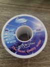
1. The solder I have is thin 0.4mm 63Sn 37Pb 1.2% (not sure what 1.2% means). Certainly not a core, too thin to be a rosin core, right? Is it good enough or I have to get a rosin core?
2. I have the lamp with 5x magnifier (LED ring around the lens) which I like a lot
3. I have this USB Microscope that I bought some time in the past but never used. May be of help now https://www.amazon.co.uk/dp/B085XZVFGT?psc=1&ref=ppx_yo2ov_dt_b_product_details
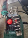
4. I found my old Soldering Iron, it is generic supermarket version (although with variable temperature control). a butchered tip no idea what I did with it. Not usable definitely. Do you suggest replace the tip, or get a new iron? Suggest something up to 50e from amazon.uk? https://www.amazon.co.uk/s?k=soldering+iron&i=industrial&rh=p_85:20930949031&dc&crid=3OC8FYNDMHC3C&qid=1710241798&rnid=20930948031&sprefix=soldering+iron,industrial,78&ref=sr_nr_p_85_1&ds=v1:gI6X0jRHGLi/F8MiB2X9KOOa3b0yQNMlEptTEj+V5Mg
5. Anything else?
 

Attachments

  • 20240312_111438.jpg
    20240312_111438.jpg
    223.1 KB · Views: 27
  • 20240312_111455.jpg
    20240312_111455.jpg
    246.8 KB · Views: 25
OP
C

catch22

Member
Forum Donor
Joined
Feb 10, 2024
Messages
68
Likes
29
Location
Ireland
For reference, I am repeating here other symptoms to be cured (apart from the main issue):
I measured the DC offset: in the Right channel it is 20mv, the Left is way higher cca 80mv.
 

Zapper

Addicted to Fun and Learning
Joined
Mar 4, 2023
Messages
608
Likes
836
Clean the tip off and tin it (melt a bunch of solder on it and let it set for several minutes, then wipe it off on damp rag). The solder is OK, it's a rosin core, 1.2%. It's a big cap so you don't need a fine tipped soldering iron. A solder remover bulb or spring loaded syringe, or solder-wick (copper braid coated in flux that wicks solder away) are valuable for removing the solder, makes it a lot easier to replace the cap.
 

Hiten

Senior Member
Joined
Nov 24, 2019
Messages
380
Likes
488
Location
India
Here is nice vintage documentary with closeups.
Soldering

Few months a go I built a Phono Preamp. I always clean the leads of parts (Capacitors, Resistors) with very fine flint paper, Clean the pcb with isopropyl alcohol, than clean with dry cloth. Apply liquid flux and solder. Use minimal amount of solder and quickly remove the soldering iron from joint.
CNC Phono 2.jpg
 

Doodski

Grand Contributor
Forum Donor
Joined
Dec 9, 2019
Messages
21,614
Likes
21,899
Location
Canada
@Doodski - an update on my tools:
Oh very cool. :D This is going to be a superb experience for you as things progress through the processes.
1. The solder I have is thin 0.4mm 63Sn 37Pb 1.2% (not sure what 1.2% means). Certainly not a core, too thin to be a rosin core, right? Is it good enough or I have to get a rosin core?
I think for now that the solder that you have is decent enough to do in a pinch. We won't be doing any soldering of those square or rectangular flat thin black chips that you may have seen and so we don't need exact solder specifications. The soldering that will be done for now is the capacitor that you are going to replace. Then to check the main PCB where the amplifier circuitry is located and some hot spots develop. That area is where problematic things usually develop due to the extreme heat that some transistors and resistors create and cause thermal cracking and solder disassociation in the joints. You'll see after you replace the capacitor in the standby circuitry. Additionally a spot to keep observant about is at the RCA and speaker connectors as they are often soldered onto the PCB in a manner that is prone to cracked solder joints leading to intermittent connections at the terminals. We'll get to that later after the capacitor replacement.
2. I have the lamp with 5x magnifier (LED ring around the lens) which I like a lot
That is a very good magnification system. I was going to mention that a lamp would be very good and voila you have one...LoL.
3. I have this USB Microscope that I bought some time in the past but never used. May be of help now https://www.amazon.co.uk/dp/B085XZVFGT?psc=1&ref=ppx_yo2ov_dt_b_product_details
Those are very handy tools that I like a lot. Good score having that on hand as a extra arrow in your quiver or a extra club in your golf bag.
4. I found my old Soldering Iron, it is generic supermarket version (although with variable temperature control). a butchered tip no idea what I did with it. Not usable definitely. Do you suggest replace the tip, or get a new iron? Suggest something up to 50e from amazon.uk? https://www.amazon.co.uk/s?k=soldering+iron&i=industrial&rh=p_85:20930949031&dc&crid=3OC8FYNDMHC3C&qid=1710241798&rnid=20930948031&sprefix=soldering+iron,industrial,78&ref=sr_nr_p_85_1&ds=v1:gI6X0jRHGLi/F8MiB2X9KOOa3b0yQNMlEptTEj+V5Mg
IF you can replace the tip with a tip designed for that model of iron that would be nice. Something in a smaller chisel shape or a small round with a slight flat spot on the tip etc would be good for learning on. Otherwise due to the nature of the soldering stuff that we will be addressing I think that if the present worn soldering iron tip gets hot and the temperature is well regulated then you can proceed with the tip that you have for now. That might change but it probably won't.
5. Anything else?
Yes, you will need a small rag or a small sponge to slightly wet with water and then scrape the hot soldering iron tip across that wet sponge or rag to clean the soldering iron tip after tinning the tip with solder and wetting the tip with solder. If you can order in some solder wick braid too that might be very helpful for you and alleviate lots of extra work and make for a much better quality outcome. You'll need somewhere around a 3mm or 4mm wide solder braid that has rosin flux in the copper braid. The solder wick is very fine copper wires that are braided together to make a flat shaped package as I mentioned in this case about 3mm or 4mm wide and maybe ~0.7 of a mm in thickness. The solder wick is used for sucking up the hot wet solder that you heat up with the soldering iron. The suction is caused by the capillary action between the small strands of copper wire in the solder wick. Solder wick is a very nice tool to have on hand. You'll need a very small spool of it so the expense won't be too high. Small spool is like maybe 2 meters of the stuff and don't purchase a 50m spool because you'll never use all of it and it does have a shelf life.

Also nice to have is a old toothbrush for scrubbing the PCB, some small cheap Que Tips of the wooden shaft variety although plastic shaft will do in a pinch and is less expensive but not by much. Use the Que Tips to scrub and mop up the isopropyl alcohol that you'll need as well for cleaning the PCB after soldering.

The schematic for the amplifier indicates that 2, 5k Ohms 10 Watt resisters are used at the power supply very large sized C141 and C142 smoothing and storage capacitors. This is very good because it means you don't need to buy a special hand held resister for discharging the power supply each time after powering ON the amplifier and then powering it OFF and then working on the circuitry doing stuff. A very nice feature that Yamaha includes in the build. This makes things very safe for the technician (you) as they work on the amp when not plugged into the wall power outlet.
A Yamaha.png

For a better service manual go to this link, create a fee account and download the service manual to your PC(s). It is much much better than the link we have been using previously. This improved and free version of the service manual will make your life easier.
 
Last edited:
Top Bottom