• WANTED: Happy members who like to discuss audio and other topics related to our interest. Desire to learn and share knowledge of science required. There are many reviews of audio hardware and expert members to help answer your questions. Click here to have your audio equipment measured for free!

Capacitor upgrade in crossover - You CAN'T handle the TRUTH! - Part 3

One thing to watch out for when replacing electrolytics with film is that the reduced ESR can change tonal balance. If I were doing that repair, I’d replace like with like rather than risking that the “upgrade” actually deteriorates the sound.

I learned this the hard way when I replaced the series tweeter cap in my MG-1s ( this was maybe 1978) with a polypropylene. The extra treble was slight but noticeable, and not in a good way.
 
We are also well aware, however, that LC-network circuit and attenuators consume (or waste) significant potions of amplifiers power and "efficiency" before actually driving the SP units
Are we? As a loudspeaker engineer I disagree with the popular version this idea (which may not be exactly what you meant). People seem to think huge amounts of power are somehow wasted but this is not true in the passband (unless on purpose, like padding down a tweeter). In the stopband the impedance is high so the consumed power gets smaller. I'd agree active crossovers can be better, for other reasons, though so far this is unfortunately crazy complex if you want to do surround.
 
The scaling is 0.1dB...The deviations are from 1 - 2.5kHz on average +0.7dB and from 2.5kHz to 9kHz about -0.2dB
I don't get this. The left scales are in volts ratio? In the "+0.7dB" region it is maybe 1.01, which would be just 0.1 dB unless my calculator is off. ??? Similar for the other "Update" graph "The scaling is 0.1dB, so the y-axis shows +-1dB" and on the left side it goes to 1.01 which is 0.1 dB for the whole graph. So I'm confused.
 
Another question regarding your interesting series of posts, what about differences of film vs electroytic after heating (semi prolonged normal use)? Did you happen to look at that?
I can't say much about that. As a hobby designer of loudspeakers, I always leave the crossovers outside the cabinet in my own projects. I have never noticed that capacitors have heated up significantly.
I had driven large 3-way floorstanding loudspeakers with a 100µF electrolytic capacitor 100VDC in series in the midrange at such high sound pressure that the hot glue with which the 20W sandcast resistors of the voltage divider were attached, were carbonized.

The electrolytic capacitors were completely inconspicuous. So, in my experience, the heating of capacitors in crossovers should not play a major role. The review of passive loudspeakers, which perform compression testing, also show no abnormalities - see for example here performed by Erin.

If anyone has any doubts about this, they should take the trouble to check the capacitors in a crossover with an IR thermometer.
Do you have a link to a single study of problematic temperature increases of capacitors in crossovers?


Alas, regarding voltages, I am left with the question what would be the effect of changing the caps of an old beloved set of speakers of mine that did originally come with 50v electrolytic capacitors.
Would recommend (as has also been said) to at least buy a cheap meter that can measure the capacitance of the old and new capacitors. If you are not afraid of the effort, you can measure crossover components for a few dollars with the free version of Arta (part called Limp), if used correctly.

Or at least make simple frequency response measurements** with REW before and after the swap to see the difference from old to new, but also to capture the difference between left and right speaker.

** Once in the near field of the affected driver and once gated measurements in 1m or more of the whole speaker.


I don't get this. The left scales are in volts ratio? In the "+0.7dB" region it is maybe 1.01, which would be just 0.1 dB unless my calculator is off. ??? Similar for the other "Update" graph "The scaling is 0.1dB, so the y-axis shows +-1dB" and on the left side it goes to 1.01 which is 0.1 dB for the whole graph. So I'm confused.
In the VCAS program used to display the measurements, there is a bug if the measurements start with 0V. I found out the reason only recently, therefore the scaling is always in the text with the measurements.
I have already exchanged a few graphics, and gradually more graphics will be exchanged. The results will not change, only the scaling shown in the graphics will be the same as in the text.
 
I can't say much about that. As a hobby designer of loudspeakers, I always leave the crossovers outside the cabinet in my own projects. I have never noticed that capacitors have heated up significantly.
I had driven large 3-way floorstanding loudspeakers with a 100µF electrolytic capacitor 100VDC in series in the midrange at such high sound pressure that the hot glue with which the 20W sandcast resistors of the voltage divider were attached, were carbonized.

The electrolytic capacitors were completely inconspicuous. So, in my experience, the heating of capacitors in crossovers should not play a major role. The review of passive loudspeakers, which perform compression testing, also show no abnormalities - see for example here performed by Erin.

If anyone has any doubts about this, they should take the trouble to check the capacitors in a crossover with an IR thermometer.
Do you have a link to a single study of problematic temperature increases of capacitors in crossovers?


Would recommend (as has also been said) to at least buy a cheap meter that can measure the capacitance of the old and new capacitors. If you are not afraid of the effort, you can measure crossover components for a few dollars with the free version of Arta (part called Limp), if used correctly.

Or at least make simple frequency response measurements** with REW before and after the swap to see the difference from old to new, but also to capture the difference between left and right speaker.

** Once in the near field of the affected driver and once gated measurements in 1m or more of the whole speaker.


In the VCAS program used to display the measurements, there is a bug if the measurements start with 0V. I found out the reason only recently, therefore the scaling is always in the text with the measurements.
I have already exchanged a few graphics, and gradually more graphics will be exchanged. The results will not change, only the scaling shown in the graphics will be the same as in the text.
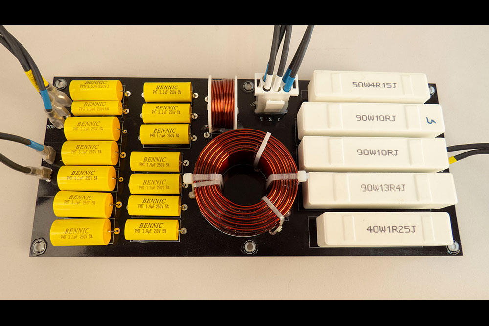
Keep in mind that heating in capacitors can only come from the resistive component, which is very small. The capacitive (reactive) part is lossless.

If you overvoltage, the failure is from arcing of the dielectric, not overheating.
 
A 4 ohm speaker that requires peak voltages of 150V requires 5625W of amplifier power :eek:
Can someone explain this quotation, it says that an amplifier can deliver much higher wattage for some microseconds (how that relates to THD)?
"This game of 'peak' value is just that. The reason is that you can mathematically play games with time and say things like for 10 mS (1/100th) of a second this amplifier can put out 50% to 100% more power. Heck, for 1 mS the power supply could dump several times its RMS load."

I have never noticed that capacitors have heated up significantly.
Ripple current heats capacitors. What is the maximum realistic ripple current/AC/music that passes through the capacitors in passive speakers? Watt's law seems to suggest that it can easily be a few amperes, which many electrolytic capacitors are not rated for. Doesn't it seem then that electrolytic capacitors do not belong in passive crossovers?
 
Can someone explain this quotation, it says that an amplifier can deliver much higher wattage for some microseconds (how that relates to THD)?
"This game of 'peak' value is just that. The reason is that you can mathematically play games with time and say things like for 10 mS (1/100th) of a second this amplifier can put out 50% to 100% more power. Heck, for 1 mS the power supply could dump several times its RMS load."


Ripple current heats capacitors. What is the maximum realistic ripple current/AC/music that passes through the capacitors in passive speakers? Watt's law seems to suggest that it can easily be a few amperes, which many electrolytic capacitors are not rated for. Doesn't it seem then that electrolytic capacitors do not belong in passive crossovers?
Ripple current is not relevant. It’s a continuous dissipation and dominated by a low frequency.

Remember that there’s also thermal inertia.
 
I have to say, I have nothing to say. After 12 pages of posts, I'm speechless. I didn't read all 12 though......I am letting SIY speak for me as I have not got the stamina to read all 12 pages. My intestinal fortitude is lacking. Probably because I didn't sleep well last night as I'm too involved in the Ukraine/Russia war.
 
Ripple current is not relevant. It’s a continuous dissipation and dominated by a low frequency.

Remember that there’s also thermal inertia.
And I forgot that most of the current goes to the woofers without passing through a capacitor or resistor, I think that's how passive crossovers are made.
 
And I forgot that most of the current goes to the woofers without passing through a capacitor or resistor, I think that's how passive crossovers are made.
Yes, the cap is usually a shunt element. There are a few odd examples where it's used as an element in the series feed but again, generally shunting something. Current is low.
 
Do you have a link to a single study of problematic temperture increases of capacitors in crossovers?
I do not, so I asked. Your answer is convincing.
Would recommend (as has also been said) to at least buy a cheap meter that can measure the capacitance of the old and new capacitors.
Absolutely, although both channels' 220uf caps (in series to the midrange) have blew (spilled). So there is no question about the need to replace them. As they were clearly very cheap capacitors, I'm tempted to change them to 220uf 100v MKP caps that I can get for pretty cheap. Curious what effect it will actually have. Thinking that if the "upgrade" is really a two sided blade, I could always replace it with a new electrolytic.
Or at least make simple frequency response measurements** with REW before and after the swap to see the difference from old to new, but also to capture the difference between left and right speaker.
Do you happen to know of REW that can adequately use a pro mic and a focusrite interface?
 
Absolutely, although both channels' 220uf caps (in series to the midrange) have blew (spilled). So there is no question about the need to replace them. As they were clearly very cheap capacitors, I'm tempted to change them to 220uf 100v MKP caps that I can get for pretty cheap. Curious what effect it will actually have. Thinking that if the "upgrade" is really a two sided blade, I could always replace it with a new electrolytic.
It will shift the tonal balance more to the midrange. If there are only electrolytic capacitors, then all of them can be replaced with film caps without any need to worry about the tonal balance. Some speakers will be designed with the ESR in mind, some will be designed with an ideal design that ignored the ESR (which means the electrolytic caps were only used for budgets and speakers will sound better there with more ideal film caps in the second example).
 
Are we? As a loudspeaker engineer I disagree with the popular version this idea (which may not be exactly what you meant). People seem to think huge amounts of power are somehow wasted but this is not true in the passband (unless on purpose, like padding down a tweeter). In the stopband the impedance is high so the consumed power gets smaller. I'd agree active crossovers can be better, for other reasons, though so far this is unfortunately crazy complex if you want to do surround.
Figure that even just shunting signal to ground means it's not getting to the driver. That's where the loss comes in.
 
In some speaker designs, the caps are specified with voltages low enough that they will fail before the drivers do. That is a good thing.
A Class-X safety capacitor could do that, but I guess the bean counters would/could prevent that. But I'm not sure that speaker drivers can handle voltage transients up to mains voltage. Maybe, someone else knows what voltage most drivers can handle.

Edit: Or a varistor?
 
Last edited:
Figure that even just shunting signal to ground means it's not getting to the driver. That's where the loss comes in.
That's true...though not life changing. I do indeed wish there was some simple solution for active crossovers with surround sound. Which sounds like a dumb oxymoronic wish when I read it :(:D
 

Seems appropriate to share here.
Looks interesting, I've seen claims against the general approach of using multi caps in parallel to reach a requested value. It was rather "audiophilic", as it degrades sound without much specific claims to back up.

If anyone has any reliable data to back up, I'm interested to see it.
Even Harman has to feed the customer with mysterious stories for the presumably well-knowing.

Back in the day another really hot thing was a bias voltage for capacitors. It should prevent crossover-distortion (like that in class A/B power amps). Horrific degradation from cross (do You feel the harsh 'ss'?) over (done and gone) distortion (evil, except for tube amps). Hence sky-rocketing benefits from JBL's genius invention were granted.

A 9V battery block is all You need to apply for audio-nirvana. Simple and effective. I only wonder if the state of battery charge was indicated somewhere? Otherwise they may have argued, that the battery might last long enough to die-off right along with the listeners hearing? Or interest that is ... :cool:

O/k, Harman, namely JBL does p/a speakers with real power capabilities in the kiloWatts. So, the current part of the vast electric power might become a problem. But I'm pretty sure, that when I hear the "singing" cap, or its malicious signal bending and breaking in the hidden, I go deaf in parallel.
 

Seems appropriate to share here.
Looks interesting, I've seen claims against the general approach of using multi caps in parallel to reach a requested value. It was rather "audiophilic", as it degrades sound without much specific claims to back up.

If anyone has any reliable data to back up, I'm interested to see it.
Measuring capacitors with an LCR meter and using film capacitors in those parts of audio circuits, where the operating voltage is higher than a few volts is reliable and what the link suggests should be dismissed.

The information in the link made me think about the article here that debunks electrolytic capacitors in parallel for crossovers. With special remembrance given to this epic quotation:
"Consider that said 'woeful' cap is vastly worse than anything you can buy, so if adding an 'ideal' 100nF cap makes so little difference to that, it follows that it will make far less difference to a half-way decent capacitor that's intended for use in crossover networks. Note that I specifically exclude bipolar electrolytic caps that are supposedly designed for crossovers. I don't use them, and I suggest that you don't either, because they are simply not stable (or good) enough for the purpose. However, consider that many high-priced commercial designs do use bipolar electros, and may well get high praise from reviewers and users regardless.

"It should be apparent that adding yet another smaller cap will have even less influence - I've seen designs using (for example) 10µF, 100nF and 10nF in parallel. The only thing this does is to create a capacitor that's a little greater in value than otherwise (10.11µF in total). The small amount of extra capacitance will change the crossover frequency ever so slightly, assuming that all values are exact, which won't be the case unless they have been measured carefully."

Film capacitors can be added in parallel in order to reach the desired capacitance, but this is because of the lack of availability and high price when they are very large.
 
Last edited:
In some speaker designs, the caps are specified with voltages low enough that they will fail before the drivers do. That is a good thing.

Not if they fail short circuit on a tweeter/midrange network...
 
Not if they fail short circuit on a tweeter/midrange network...
Well, a cap that fails that way wouldn't be one an engineer would choose for that purpose, right?
 
Back
Top Bottom