• Welcome to ASR. There are many reviews of audio hardware and expert members to help answer your questions. Click here to have your audio equipment measured for free!
One member from DIYAUDIO suggested this article: http://www.tronola.com/html/maximize_tube_life.html that looks at ways to substantially improve the lifetime of the power tubes. I read it and it does make some solid points. In short, it looks at all the reasons why a tube amp would have an arc inside the output tubes and it comes with a practical solution to these problems. The solution presented in the article is to initially apply the 6.3V for the filaments of all the tubes. Wait 30+ and apply the B+ voltage on the input and driver tubes only. Wait another 10s and then apply the B+ to the power tubes. At power off, we disconnect the B+ from the output tubes as quick as possible and then disconnect the B+ from the input and driver tubes.

In my case, I did a test with the PHONO pre-amp removed and I did not have the "thump" at power off. So I tried to increase the output capacitance of the +/-10Vdc regulator. You know, throw some microfarads at the problem :). This did not remove the problem completely, but it improved the situation a bit. At power OFF, I see the woofer moving a bit as all the capacitors discharge, and right at the end I hear a smaller "thump". I'll have to wait for the evening to see if there is still that faint light effect (it's too bright to notice during the day). I'll think of a more elegant solution but for now it will have to do. I might want to power the PHONO pre from a separate transformer and regulator but from the same transformer as it is now. I do not want to add another small toroidal inside as I already have two :) , one for the filament voltage of the input and driver tunes (that gets rectified to have 6.3Vdc) and a second one that is used to generate all the control voltages for the tubes and to power the PHONO preamp.
 
I managed to update the schematics for the amplifier and the power supply.
 

Attachments

  • power_amp_V2.pdf
    64.4 KB · Views: 254
  • Power_supply.pdf
    62 KB · Views: 170
I will post some pictures with the "final" product soon. Before I do that, I was thinking of adding a nice milliamp meter on the front panel so that I can see the bias current of the KT88s. I would also like to be able to switch between the four tubes. The thing is that I do not want to wire the cathode current through the windings of the analog ammeter. So this leaves me with the only option of measuring the voltage drop over the 3.3R cathode resistors. This means that will most probably need a V-I transconductance stage. This will convert the voltage drop over the cathode resistor (~190mV) into mA that will be displayed using the analog milliamp meter. I will also use a variable resistor in order to "calibrate" the whole thing. Are there any other solutions?
 
Re toroids, their issue is the sensitivity to any idle current offsets. If there's a solid autobias circuit to keep the halves in near-perfect balance, toroids can work very, very well (I say "can" because I don't know that particular company). If you have a few milliamps of unbalance, they will not work well at all. The Hammonds are reasonably OK; if you can find James, they are some of the best out there. I have heard good things about Heyboer, but no personal experience.
For my push pull KT88 I used a fancy bias board from the firm Tentlabs ( https://www.ringkerntrafo.nl/shop/high-end-audio/tentlabs-modules/369/negative-bias-supply.html ).
 
I will post some pictures with the "final" product soon. Before I do that, I was thinking of adding a nice milliamp meter on the front panel so that I can see the bias current of the KT88s. I would also like to be able to switch between the four tubes. The thing is that I do not want to wire the cathode current through the windings of the analog ammeter. So this leaves me with the only option of measuring the voltage drop over the 3.3R cathode resistors. This means that will most probably need a V-I transconductance stage. This will convert the voltage drop over the cathode resistor (~190mV) into mA that will be displayed using the analog milliamp meter. I will also use a variable resistor in order to "calibrate" the whole thing. Are there any other solutions?
Why not just scale the meter so that the correct current is reported? That is, make up a new overlay for the meter scaled in mA and apply that over the existing face on the meter. That's how I did it for a project I did.
 
Why not just scale the meter so that the correct current is reported? That is, make up a new overlay for the meter scaled in mA and apply that over the existing face on the meter. That's how I did it for a project I did.
The thing is that I have a milliamp meter not a millivolt meter. This means that I have to insert it in series with the current I want to measure. If I just place it over the 3.3R cathode resistors then I will add the resistance of the meter (0.7R) in parallel with the 3.3R. And this will make a bit difficult to switch between the tubes.

My approach would be to implement something like in the picture below:

1668542061739.png


R3 is the cathode resistor, R2 would be the milliamp meter and R5 would be adjustable. This circuit has a very low error on the scale I'm interested on. It will be supplied from one of the 6.3Vdc regulators that I use for the filaments of the input and driver stage. During normal operation I have around 190mV on the 3.3R resistors (~57mA) and the circuit will draw around 58mA from the 6.3Vdc supply. I will add a rotary switch before R4 and in this way I will be able to switch between all four tubes.
 
I missed that in my reply. You would have to go inside the milliammeter and remove the burden resistor. Burden resistor is the shunt you described. My oversight.
 
I missed that in my reply. You would have to go inside the milliammeter and remove the burden resistor. Burden resistor is the shunt you described. My oversight.
Yes indeed. One option would be to take the shunt resistor out. In reality it's just a loop of wire. So, I just have to cut it and it should then behave like a voltmeter. I then add a voltage divider with one resistor adjustable in order to align the values. After cutting the shut wire, the resistance of the meter itself is around 13R. By adding a ~73R resistor in series with the meter it should be ok. I will have full scale at 330mV over the 3.3R resistors. The only thing is that when the meter is connected, I will add 2.2mA of current through the tube I'm measuring (on top of the 57.6mA that goes through the tube). This will definitely create a small imbalance but I'm not sure whether this is something to worry about or not.
 
Last edited:
So long as all the tubes share the same amount of error in the bias setting, they will still be balanced (i.e. the same) in their adjustments. That amount of error is unlikely to noticeably affect performance.
 
I decided to use an opamp as a buffer before the 73R resistor and the meter. In this way I know for sure that the current going to the meter will not affect the current going through the tubes. I had a few AD8655s from another project and apart from the odd pinout, these should work like a charm. And indeed, these worked just fine. The only slight inconvenience was that AD8655 has a max supply voltage of 5.5V. But tat was ok as I had a few 5V LDO regulators laying around :) (I know, I have many parts just laying around, maybe too many :facepalm:). I also added a rotary switch (non-shorting) on the input of the opamp and now I can see the current through all four tubes. I think that this concludes this project. At least for now :). I will probably post a separate thread with the "official" measurements of the finished product.
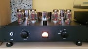
 

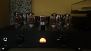
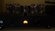
Attachments

  • 20221119_151834.jpg
    20221119_151834.jpg
    163 KB · Views: 176
  • 20221119_151848.jpg
    20221119_151848.jpg
    99.9 KB · Views: 182
  • 20221119_151902.jpg
    20221119_151902.jpg
    80.3 KB · Views: 161
  • 20221119_153421.jpg
    20221119_153421.jpg
    84.8 KB · Views: 202
@SIY I just noticed that there is a channel imbalance. The left channel has an output 100mV lower than the right one. For an output voltage of 2.4Vrms on the left, I have 2.5Vrms on the right. I'm not sure what is acceptable and if this imbalance is in any way audible. Is this something that you get with tube amps? Is it coming from the tubes themselves? If it's not the valves, then I would have to take the thing apart and see where it' coming from :)
 
@SIY I just noticed that there is a channel imbalance. The left channel has an output 100mV lower than the right one. For an output voltage of 2.4Vrms on the left, I have 2.5Vrms on the right. I'm not sure what is acceptable and if this imbalance is in any way audible. Is this something that you get with tube amps? Is it coming from the tubes themselves? If it's not the valves, then I would have to take the thing apart and see where it' coming from :)
Did you check the values of the feedback resistors? That said, this is only a 0.3dB imbalance.
 
@SIY I just noticed that there is a channel imbalance. The left channel has an output 100mV lower than the right one. For an output voltage of 2.4Vrms on the left, I have 2.5Vrms on the right. I'm not sure what is acceptable and if this imbalance is in any way audible. Is this something that you get with tube amps? Is it coming from the tubes themselves? If it's not the valves, then I would have to take the thing apart and see where it' coming from :)
That's about a 0.35dB difference; may well not be audible. As for tube amps, variation like that is not unreasonable. Change tubes and you may well get a different, even larger number. With S.S. amps, you have a lot more open loop gain and the extra feedback will tend to shrink differences in stage gain. It's also possible that a plate or cathode resistor is out of spec, so you could measure them and see. Of course, dangerous high voltages are present in tube equipment, and can linger in charged caps even after the power has been off for a time. Check with voltmeter before handling anything.
 
Did you check the values of the feedback resistors? That said, this is only a 0.3dB imbalance.
I know it's only about 0.3dB and most probably it's not audible. The thing și that I had a vague impression that the balance is not 100% and that is why I did the measurements. It confirmed that the right one is a bit louder. If I change the listening position I can't hear it anymore :). The may suspesc are feedback resistors but I do not want to open it now. I will leave it as it is for now and I will open at some point and I will investigate. I've also added a small pre-amp, I call it an active gain stage, before the power amps so that I can have full power with different input sources. That pre-amp is not the source of the imbalance as I measured it a lot before adding it inside.
 
S
I know it's only about 0.3dB and most probably it's not audible. The thing și that I had a vague impression that the balance is not 100% and that is why I did the measurements. It confirmed that the right one is a bit louder. If I change the listening position I can't hear it anymore :). The may suspesc are feedback resistors but I do not want to open it now. I will leave it as it is for now and I will open at some point and I will investigate. I've also added a small pre-amp, I call it an active gain stage, before the power amps so that I can have full power with different input sources. That pre-amp is not the source of the imbalance as I measured it a lot before adding it inside.
Swap tubes left for right and see what the balance looks like.
 
I think I figured it out. I did several measurements at four gain settings (pot positions) and the results are shown in the table below:

1694850474182.png

LEFT and RIGHT are output voltages in mV (on 8OHM load) and LOW, MID, HIGH and MAX are the gain settings of the pre-amp, basically positions of the potentiometer.
By the looks of the data, it seems that the pot in the pre-amp is not great. If it were an issue with a feedback resistor or a tube, the difference in dB should have been the same across potetiometer settings. But it isn't. The delta is at its max at the mid position of the pot. This to me, indicates that the pot is not of high quality :). I have no other explanation for this. If you guys have a different opinion, please let me know. Thanks.
 
I think I figured it out. I did several measurements at four gain settings (pot positions) and the results are shown in the table below:

View attachment 312315
LEFT and RIGHT are output voltages in mV (on 8OHM load) and LOW, MID, HIGH and MAX are the gain settings of the pre-amp, basically positions of the potentiometer.
By the looks of the data, it seems that the pot in the pre-amp is not great. If it were an issue with a feedback resistor or a tube, the difference in dB should have been the same across potetiometer settings. But it isn't. The delta is at its max at the mid position of the pot. This to me, indicates that the pot is not of high quality :). I have no other explanation for this. If you guys have a different opinion, please let me know. Thanks.
Oh, if there's a pot involved, the imbalance you're getting is better than usual. Stepped attenuators might be a touch better (at a huge cost and size premium), but only a touch. You have a good result there.
 
So, what do you think about it now? I built a kit WAD KT88 amp in 2001. Many prefer 6550 tubes, you may well prefer the mids.
 
I think I figured it out. I did several measurements at four gain settings (pot positions) and the results are shown in the table below:

View attachment 312315
LEFT and RIGHT are output voltages in mV (on 8OHM load) and LOW, MID, HIGH and MAX are the gain settings of the pre-amp, basically positions of the potentiometer.
By the looks of the data, it seems that the pot in the pre-amp is not great. If it were an issue with a feedback resistor or a tube, the difference in dB should have been the same across potetiometer settings. But it isn't. The delta is at its max at the mid position of the pot. This to me, indicates that the pot is not of high quality :). I have no other explanation for this. If you guys have a different opinion, please let me know. Thanks.
The results you show look excellent; there's nothing to worry about. You won't notice that level of imbalance at all during listening.
 
Back
Top Bottom