• WANTED: Happy members who like to discuss audio and other topics related to our interest. Desire to learn and share knowledge of science required. There are many reviews of audio hardware and expert members to help answer your questions. Click here to have your audio equipment measured for free!

Audiolab DC Blocker 6 - Inside Pictures

DK11706

Member
Joined
Nov 28, 2019
Messages
22
Likes
5
Hi,

Can someone tell me how much DC this baby will block, I don't know that much about components and I'm pretty sure that the support guy from Audiolab was wrong.

Please feel free to comment on the design it self, is it any good or should I return it. It does stop some of the pops I have in my speakers when I turn on the light, but not all, so maybe I need something more powerful, hence I need to know how much DC it blocks :)


IMG_1251.jpg


IMG_1265.jpg


IMG_1266.jpg


IMG_1272.jpg
 

JayGilb

Major Contributor
Joined
Jul 22, 2021
Messages
1,384
Likes
2,356
Location
West-Central Wisconsin
With a single bridge rectifier per ac outlet, you will have two diode drops of .7v which totals 1.4v of of dc blocking.

Edit: Maybe your light switch is arcing (not sure what type you have), have you tried to replace the switch ?
 
OP
D

DK11706

Member
Joined
Nov 28, 2019
Messages
22
Likes
5
Thank you, 1.4v per outlet is great, but also what I expected from reading about the smaller one. The support guy said only 500mv in total then changed it to 500 mv per output.

The light switch is fine (new), the pops are related to the LED bulbs (GU10) with integrated transformers, they are known for their bad behavior, but thanks for the tip :)
 

AudiOhm

Senior Member
Joined
Oct 27, 2020
Messages
411
Likes
410
Location
London, Ontario, Canada
If you know the problem is the bulbs, why would you spend money on something else to fix it?

What brand of GU10 LED Bulbs do you have?

I have a few of these in my home, made by GE, no problems...

Ohms
 

solderdude

Grand Contributor
Joined
Jul 21, 2018
Messages
16,066
Likes
36,478
Location
The Neitherlands
DC blockers can lower audible hum in transformers IF these hum because of DC.
Sometimes a give away is that a device hums a bit more or a bit less over the coarse of a day or even longer.

This device does have a common mode filter and surge protection (for short pulses) which may or may not help in certain cases with other mains gremlins.
 
OP
D

DK11706

Member
Joined
Nov 28, 2019
Messages
22
Likes
5
I did some more digging and the LED bulbs are not replaceable after all, and the pop/crackle is back with a vengeance. The light switch might be the issue, so I will try installing a dimmer switch, they seem to work better around the house.

The quality and design of the unit is very nice, if anyone is considering buying one. It did not fix my problem, so I'm going to return it.
 
Last edited:

radix

Major Contributor
Joined
Aug 1, 2021
Messages
1,409
Likes
1,349
The LED fixtures surely are replaceable, but they likely have integrated bulbs so you replace the whole fixture.

For the $500 of the DC blocker, you could likely call a real electrician, describe the problem, and see if he can come out and fix the problem. The 4" LED can lights are not very expensive.
 

earlevel

Addicted to Fun and Learning
Joined
Nov 18, 2020
Messages
551
Likes
779
Hi,

Can someone tell me how much DC this baby will block, I don't know that much about components and I'm pretty sure that the support guy from Audiolab was wrong.

Please feel free to comment on the design it self, is it any good or should I return it. It does stop some of the pops I have in my speakers when I turn on the light, but not all, so maybe I need something more powerful, hence I need to know how much DC it blocks :)
A DC block like this is simply a highpass filter, which blocks DC and very low frequencies and lets audio pass. In the time domain, that make the electrical signal centered on average, instead of being offset from ground one side or the other. IF you such a DC offset, getting rid of it has the positive effect of centering the signal so you have better headroom on you amp stages and your speaker excursion bounds—avoiding unnecessary clipping.

Second, it reduces the potential problem of popping or thumping when you turn on the power amp. If nothing is coming out of your preamp or other upstream device, such pops won't be too bad, but if said upsteam device has a DC offset, big pop/thump.

But turning on lights, motors, or other equipment that draws a lot of current, produces a glitch, a transient. Most likely in the power that feeds the amp, causing the spike to end up in your speakers. Blocking DC won't help that. It could be due to a number of things, but for example if you have poor wiring, insufficient gauge wire running a long distance from the panel. If so, you might also be prone to ground loops (AC hum)—have any of that?
 
OP
D

DK11706

Member
Joined
Nov 28, 2019
Messages
22
Likes
5
No ground loops issues, and wiring gauge is also okay, bad wiring could be the root cause but I hope not, the house is brand new and all the wiring runs inside the walls.

I'm still voting for the light switch or the LEDs, I have the same LEDs other places in the house but they are using a dimmer switch, and there are no issues with pops when turning them on/off, so my guess is that the LEDs are causing the issue but the dimmer switch has a built-in resistor that eliminates it. My next move is to install the dimmer switch in the room with the popping light switch, and see what happens :)
 

radix

Major Contributor
Joined
Aug 1, 2021
Messages
1,409
Likes
1,349
No ground loops issues, and wiring gauge is also okay, bad wiring could be the root cause but I hope not, the house is brand new and all the wiring runs inside the walls.

I'm still voting for the light switch or the LEDs, I have the same LEDs other places in the house but they are using a dimmer switch, and there are no issues with pops when turning them on/off, so my guess is that the LEDs are causing the issue but the dimmer switch has a built-in resistor that eliminates it. My next move is to install the dimmer switch in the room with the popping light switch, and see what happens :)

I think someone mentioned checking the switch. It could have a loose wire or wire nut that is causing arcing when turned on.
 

restorer-john

Grand Contributor
Joined
Mar 1, 2018
Messages
12,734
Likes
38,971
Location
Gold Coast, Queensland, Australia
I'm still voting for the light switch or the LEDs, I have the same LEDs other places in the house but they are using a dimmer switch, and there are no issues with pops when turning them on/off, so my guess is that the LEDs are causing the issue but the dimmer switch has a built-in resistor that eliminates it. My next move is to install the dimmer switch in the room with the popping light switch, and see what happens

The LEDs lights will have (internally) a bridge rectifier, followed by a mains rated filter electrolytic capacitor, which then feeds a small SMPS to run the LED bulb assembly.

The more LEDs you have hanging off one switch, the greater than instantaneous current when you flick the switch. A dimmer works in a completely different way- one byproduct is a much gentler turn on characteristic. However, depending on the dimmer design, you may have a problem with RFI.
 

24U

Member
Joined
Dec 5, 2021
Messages
18
Likes
2
A quite cheap and not very sophisticated filter design, offering a substandard DC-filtration, unless the reqtifier bridge is not spec'd with higher forward voltage diodes. The decoupling is very rrudimentory as well and will do some good, but since no resistor loads are implemented it will not cancel possible resonances.
Audiolab did not even implement the most standard cabling for lowering stray and reduce pick-up by twisting the cables inside. The positive side, is that there are filtrations on each plug, reducing the mutual interference. Schottky diodes, CM choke and additional large C with R as loads, and voila' you would have had a far better filter.
In Sweded measures of up to DC-shift at 3 volt has been registered. The modern domestic electrical appliances is maybe more energy efficient, but is causing some serious mains network issues. My own plasma TV is backfeeding a hefty 700 mV up to 1 volt ripple noise to the mains network. It took some serious designing and high spec'd components to get rid of the DC and ripple at my home.
 

Snoopy

Major Contributor
Joined
Jul 19, 2021
Messages
1,645
Likes
1,247
Would a DC blocker do anything good when using SMPS amps and DACs?

I'm thinking about my setup that shares a powerstrip with my oled TV and router/ Playstation stuff.
 

gamerpaddy

Member
Joined
Mar 6, 2022
Messages
71
Likes
320
Location
Germany
SMPS eat DC and AC, it doesnt matter. it comes in, gets filtered a little, goes trough a rectifier and becomes DC anyways.


i once had a ceiling fan, when it ran it was dead silent besides the wind noise... most of the time.
but each day at a certain time, it started audibly humming.
that was caused by a little dc offset on the mains caused by whatever my neighbours turned on in that moment. a dc blocker fixed this issue.

rod elliot has a helpful article about it https://sound-au.com/articles/xfmr-dc.htm
 

24U

Member
Joined
Dec 5, 2021
Messages
18
Likes
2
SMPS eat DC and AC, it doesnt matter. it comes in, gets filtered a little, goes trough a rectifier and becomes DC anyways.


i once had a ceiling fan, when it ran it was dead silent besides the wind noise... most of the time.
but each day at a certain time, it started audibly humming.
that was caused by a little dc offset on the mains caused by whatever my neighbours turned on in that moment. a dc blocker fixed this issue.

rod elliot has a helpful article about it https://sound-au.com/articles/xfmr-dc.htm
True in one sence, the backfed noise is however not very benign to any device with linear transformer based psu's
 

solderdude

Grand Contributor
Joined
Jul 21, 2018
Messages
16,066
Likes
36,478
Location
The Neitherlands
True in one sence, the backfed noise is however not very benign to any device with linear transformer based psu's

Why would this be a problem for transformer based PSU's ?
There are E-I transformers, toroidial, R core, well separated bobbins, even foil screened bobbins etc. All of these have a different capacitive coupling for common mode and even differential mode 'crap'. And even then it is the signal routing/PCB design that determines the most what gremlins could possibly make it into the audio path, if they get there.
 

24U

Member
Joined
Dec 5, 2021
Messages
18
Likes
2
Why would this be a problem for transformer based PSU's ?
There are E-I transformers, toroidial, R core, well separated bobbins, even foil screened bobbins etc. All of these have a different capacitive coupling for common mode and even differential mode 'crap'. And even then it is the signal routing/PCB design that determines the most what gremlins could possibly make it into the audio path, if they get there.
The thing is, torodial transformers are rarely just with shields. That is an axception, though it is a very efficient way to halt the noise AND the DC, if giving the core a bit headrrom, already in the transformer. The PCB is very good way also halt the noise. But there are commonly some disturbing flaws in the execution of the PCB's;
I/O's are not decoupled so in almost any ofthe designs I have scrutinized, interconnects shield noise is landed right on to the PCB instead of grounded to chassis. The stray infects the so delicate 0 volt ref voltage to numerous IC's including the DAC chip. Do not take just my word for it, it is a friend of mine, studio technician, Master of Science educated, at least 40 years in the profession, who rebuild DAC's like dCS, but also cheaper versions like Topping D90SE, who claims that ground ref is is a design flaw in it self as are many other areas. The ground is then also challanged by the standard procedure of soldering e.g. pin1 but also shields in USB's, I2S UI, etc in the PCB. The PCB ground should not be used to land noise from cable shield in my opinion. So when decoupling, you should be able to trust the ground you decouple to., but you cannot. One thing so often overlooked is the use of filter and buffert electrolythic caps. They are in the analogue domain often soldered i pairs from the positive and negative to the ground, instaed of caring for the ground by having one twice the size directly between positive and negative only. The filter caps for purely decoupling is wired equally. Why? Some brands use local regulators some do not. In my opinion all voltage regulators should of top class with a few microvolts ripple if any, and locally, with a large buffer, zobel and decoupling almost at the same pin as it is designed to feed. Hifi grade el caps is a myth. The modern 105 degree offers in general better life expectancy and radically lowered internal losses for decoupling.

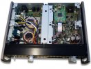
While studying various designs I stumbled across a TEAC DAC, that I personally found interesting as it took a grip of the dirty USB cable shield. It lands the USB port at separate pcb, hard coupled to chassis by a screw and just millimeters from the port, minimizing the lead reactans, the entire PCB is grounded to chassis. This is an example of a good design. Others in that DAC could be questioned in my opinion. Could not see, e.g. any signs of a grounded lead out from an electrostatic shield in the transformers.

I agree with all you say, that is how it is supposed to be, but when I see the actual designs, I see a component choices, designs and U/I's that do not support that, sorry.
 

Attachments

  • Teac DAC.jpg
    Teac DAC.jpg
    77.3 KB · Views: 234

solderdude

Grand Contributor
Joined
Jul 21, 2018
Messages
16,066
Likes
36,478
Location
The Neitherlands
The actual problem is not that everything should be designed as optimal as possible. It should be designed good enough.
You often do not need super low noise regulators, you often do not need the lowest possible ESR caps. They are all design choices made by requirements, availability of parts and price.
Wiring, PCB design often are far from optimal. But lets face it. Only very few people are really bothered by ground loops and they all can be solved by finding the loop(s) and breaking it/them.

DC blockers like the one discussed are not going to help here. Sure the common mode filter on the input can lower common mode crap from the mains a little and could lower the crap generated by the connected gear but the ground loops (which are the culprit) is not broken anywhere and crap coming from SMPS connected to the outlets of the device will happily reach the other connected devices unattenuated.

That is regardless of linear or SMPS connected to it and it won't change anything inside the actual devices.
 
Last edited:
Top Bottom