• WANTED: Happy members who like to discuss audio and other topics related to our interest. Desire to learn and share knowledge of science required. There are many reviews of audio hardware and expert members to help answer your questions. Click here to have your audio equipment measured for free!

Adding SPDIF Output to Sony CDP-101 - Jitter-Free PLL Needed

Herbert

Addicted to Fun and Learning
Joined
Nov 26, 2018
Messages
530
Likes
437
Dear friends,
I already added SPDIF-outputs to secend gen. CD-Players:
CX23035-SPDIF Out
No I would like to add it to the CDP-101, one of the very first CD-Players.
Mine is in mint condition and ran for about 200hours. I bought it first hand from a dealer in 2014
who stored 3 units for about 30 years.

The big problem:
Digital outputs ICs like the DIT4192 or WM8805 work with "fs" (Frames I guess) that are based on multiples of a 4.2336MHz clock.
As one example, a clock of 16.9344MHz (four times of 4.2336MHz) generates 384fs.
99% of the CD-Players sold are based on the multiples of 4.2336MHz.
In the link above, the player works with a clock of 8.4672MHz, which is the exact half of 16.9344MHz.
Both clocks can be easily synced and the DIT4192 grabs it´s 384fs from the 192fs source.
Works perfectly for more than a decade.
But the Sony CDP-101 is an exception. It runs on 8.6436MHz, which equals 196 fs, a ratio of 1,959183673469388 to 16.9344MHz
Reason is the RAM/Decoder IC CX7934.

40 years ago, this schematics are from September 1983, Philips had the same problem: They used the CX7934 IC from Sony in the CD-200 and CD-300, but ran the rest of the already on 4.2336MHz:

CX7934-CD303.jpg
So they built a PLL. To my understanding, A813 on the far right sends 8.6436MHz to the CX7934, which emits the LR-Clock of 44.1kHz over A812 back to the PLL, where it is synced with
the 44.1KHz derived from a 4.2336MHZ base:
Clock-CD303.jpg

The IC on the far right is SN74LS624N. The only IC that is obsolete, but I bought one. All other IC are still available. Here is the same schematics cleaned up:
pll.png

So I could rebuilt it, using a 16.9344MHz external clock that also provides 4.2336MHz, replacing IC 6660 on the left.
But this circuit must be very jittery! Any advises to claean up the jitter or for trying a different approach?
The easiest solution could be a SPDIF transmitter that does not need a master clock and generates it from the Bitclock and L/R Clock,
but to my knowledge, such transmitters do not exist.
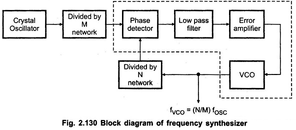
Another approach might be to sync the Sony CDP-101 master clock 8.6436 to 16.9344MHz.
Division-multiplication would look like this:

PLL-Ratio.jpg

So, any advice on the matter?
BTW, data sent from the CX7934 is the same as the later CX23035: 16-Bit Right-Justified, twos complement, MSB first.
All the best, Herbert
 
Last edited:
OP
H

Herbert

Addicted to Fun and Learning
Joined
Nov 26, 2018
Messages
530
Likes
437
No one to give advice? 40 years after the PLL design given above,
it should be relatively easy to built a PLL from 16.9344MHz to 8.6436MHz...?
Or, what might be easier, to extract SPDIF from Data, LR/Clock and Bitclock without the need of a master clock?
But none of the SPDIF Transmitters I know , WM8804/05 DIT4192/4096, can do that
The CX7934 can also be set to send parallel data instead of serial data.
Maybe SPDIF can be easier extracted from parallel data...? (But I guess not)
All the best, Herbert
 

voodooless

Grand Contributor
Forum Donor
Joined
Jun 16, 2020
Messages
10,408
Likes
18,379
Location
Netherlands
Maybe something with an ASRC will do it?


I'm also not sure a PLL would help here? A clock clocks something. Making a new skewed one, will probably mangle the data as well.
 

voodooless

Grand Contributor
Forum Donor
Joined
Jun 16, 2020
Messages
10,408
Likes
18,379
Location
Netherlands
OP
H

Herbert

Addicted to Fun and Learning
Joined
Nov 26, 2018
Messages
530
Likes
437
Well, I did start the thread at diyaudio, but frankly that place ( I am a user there for about two decades) has become a madhouse.
It has become a matter of chance who leads the discussion. In another thread, a user was extremely helpful in designing a tiny mic-preamp for my
camera gear. A real "Guardian Angel". This is what those forums should be about: Help those with lesser knowledge.

But in the thread linked above I was given the advice to use the Philips design posted here but then the user
panned it as crap without stating why - not very useful, see the last posts at diyaudio.
Another one threw little bits at me and expected me to dig deep into the literature.
No time for this and simple questions were still not answered.
In contrast, this is audioSCIENCEreview - in the past I got more useful and helpful answers here.
Back to topic:
I scrolled though the SRC4293 datasheet, but it looks like it needs a controller and clock
The SPDIF-transmitters I mentioned are easier to implement, without controller.
Maybe there are simpler / better PLL-designs than the one I posted?
Simpler / better means going "directly" - without the use of the L/R-Clock - from 16.9344MHz to 8.6436MHz,
with less jitter and fewer parts...? All the best, Herbert
 

MCH

Major Contributor
Joined
Apr 10, 2021
Messages
2,659
Likes
2,274
The easiest solution could be a SPDIF transmitter that does not need a master clock and generates it from the Bitclock and L/R Clock.
Very cool project, good luck with it!
Your post is well above my pay grade, but in case, to the question above, I believe ES9080 DAC chip allows to set bitclock as PLL clock source (register 193).

ES9080 has two spdif outputs besides the DACs that you could use for your project.

(sorry if all this makes no sense, it could well be the case)
 
OP
H

Herbert

Addicted to Fun and Learning
Joined
Nov 26, 2018
Messages
530
Likes
437
Needs a microcontroller. I would like to prefer hardware mode.
Have you tried asking @restorer-john
I hope he joins the discussion! He claims to have four CDP-101... https://www.audiosciencereview.com/...forum-tda-1541a-dac-review.29432/post-1031480
ES9080 has two spdif outputs besides the DACs that you could use for your project.
Hmmm: "Configured by Microcontroller or other I2C Source" There is also no statement whether the ES9080 would "understand"
the old Sony - data format, a standard nevertheless back then:
16bit, right justified, two's complement, MSB first.
I assume further details on the ES9080 are only availbale by signing an NDA with EssTech?
The DIT4192 can be directly fed with this 16-bit format, i.e. coming from CX23035.
In later players, the CDP - 101's DAC called CX20017 was fed by the CX23035.
As its input format of the CX20017 DAC cannot be alterd,
I assume the CX7934 in the CDP-101 puts out the same data-format as the later CX23035.

BTW I modded my Nakamichi OMS-5EII with the much earlier ES9018DAC.
The CX23035 SPDIF Out mentioned in the beginning
was in preparation to this:

Besides a PLL - could SPDIF be extracted from Bitclock / L/R Clock and Data using some logic ICs?

And this fellow faced the same problem back in 2015, but the machine was a Philips...

He claims no reclocking was needed but when I read the text after "The long way to SPDIF" it reads like he had do multiply /
divide the master clock of 4.2336MHz...?
 
Last edited:

MCH

Major Contributor
Joined
Apr 10, 2021
Messages
2,659
Likes
2,274
Hmmm: "Configured by Microcontroller or other I2C Source"
Correct, no hardware mode. But the i2c programming is quite straightforward.
There is also no statement whether the ES9080 would "understand"
the old Sony - data format, a standard nevertheless back then:
16bit, right justified, two's complement, MSB first.
I assume further details on the ES9080 are only availbale by signing an NDA with EssTech?
No idea. But if you can send me a file in the said format that can be played with ALSA, I can test it for you. edit: oh well I would need the IC in the cd player to generate the i2s in that format :-/
 
Last edited:
OP
H

Herbert

Addicted to Fun and Learning
Joined
Nov 26, 2018
Messages
530
Likes
437
Correct, no hardware mode. But the i2c programming is quite straightforward.

No idea. But if you can send me a file in the said format that can be played with ALSA, I can test it for you.
Therefor I would need to "catch" it. But it is an older standard of serial data exchanged between the decoder and external digital filter or DAC in CD players.
The still active DIT4192 works with it. This is why I am asking for a PLL, because to my understanding, the DIT4192 needs a clock to grab
the fs ( BTW is it frames? For what does fs stand for?) from the Data.

And here's something you don't see everyday:
Ha! Mine came with a wine-red cloth (to clean the discs) and a catalogue of the the first Compact Discs released. BTW all CDP-101 seem to have a tiny scratch along the front panel, probably from the assembly line. We discovered this in the German Hifi-Forum, a user exaggerated it:
cdp-101_402891.jpg

For those of you playing along at home, this is relevant part of the CDP-101 schematic:
Interestingly in this schematic / the CDP-101, the Xtal 502 is about 6.64MHz. In the almost identical players that came later,
like the CDP-701, X502 is 8.6436MHz and T502 is omitted:
701.jpg

8.6436 is 196fs.
Basic question about PLL: When both frequencies run parallel, are they rigidly coulped, even when the divider is not even?
 

restorer-john

Grand Contributor
Joined
Mar 1, 2018
Messages
12,733
Likes
38,965
Location
Gold Coast, Queensland, Australia
BTW all CDP-101 seem to have a tiny scratch along the front panel, probably from the assembly line. We discovered this in the German Hifi-Forum, a user exaggerated it:

Probably from the machine that applied the "it's a Sony" sticker. We know it was a machine, because there is no way Nakajima would have allowed the stickers to be so poorly aligned on his player.

I'll have to have a look at mine to see if it has the same scratch.
IMG_2468.jpg
IMG_2469.jpg
IMG_2470.jpg


No scratch.
 
Last edited:
OP
H

Herbert

Addicted to Fun and Learning
Joined
Nov 26, 2018
Messages
530
Likes
437
No scratch.
It is best to be seen when the surface reflects light or in backlit sunlight:
On my "new" CDP-101:
Scratch NEW Sony-01.jpg

On a heavily used one that serves for spare parts. Same shape! Notice that the "C" in CDP is unharmed, so it must have happened before silk printing the lettering.
Scratch used Sony-02.jpg

As the scratch consist of two parabolas, maybe it comes from the mold in which the plastic of the front panel was injected.
But then the paint should have covered it. BTW, do you know what kind of paint was used back then? The paint must have been very opaque and had to dry very quickly for fast further processing.
Here are the cloth and catalogue shipped with the CDP-101:
IMG_2649.JPG
 
  • Like
Reactions: MCH

restorer-john

Grand Contributor
Joined
Mar 1, 2018
Messages
12,733
Likes
38,965
Location
Gold Coast, Queensland, Australia
What are the serial numbers of your players or dates of manufacture? Or date codes on the ICs can pin down when they were made.

Mine has absolutely no scratch like you show. The other 3 in the storeroom- who knows...
 
OP
H

Herbert

Addicted to Fun and Learning
Joined
Nov 26, 2018
Messages
530
Likes
437
Did you check when the surface reflects light?
A German user has four CDP-101, like you, and all four have the same scratch, see post #61 in this link:
Translation from German:
"...just out of curiosity, I took a closer look at my own CDP 101... All 4 of them do indeed have the same scratch on the front panel... I have never noticed this before... but it seems to be production-related, as it is identical in all cases... roughly as indicated in the picture."
The picture mentioned is also in post #13 of this thread
Serial numbers, the "new" CDP-101 that was stored in its original, unopened packing for 30 years:
New.jpg

The old and heavily used one:
Old.JPG

Back to topic:
The CDP-101 runs with 8.6436MHz, which equals 196 fs.
The digital transmitters available that work in hardware mode and read 16bit right justified,
like the DIT4192 / DIT4096 run with
11.2896MHz = 256fs
16.9344MHz = 384fs.
22.5792MHz = 512fs
(I leave the Wolfson WM8804 out.)
To my understanding, the masterclock of i.e. 16.9344 is needed to "extract" the fs from the stream of data / bitclock / LR-clock.
Easy, when the player and DIT share the same master clock or if the clock of the player can be divided into integers,
then you only need a flip flop, as shown in the circuit of the CX23035 at the very beginning of this thread.
So, if no one comes up with a solution to generate the fs from data / bitclock / LR-clock without the need of a master clock,
I would need a PLL.
 
Last edited:
OP
H

Herbert

Addicted to Fun and Learning
Joined
Nov 26, 2018
Messages
530
Likes
437
Are you shure that you can not use cs8421 in hw mode?
Thanks! You wrote CS8420 in post #7.
There is a hardware mode for the CS8421, SRC can be bypassed and it looks like
up to 96kHz, no external clock is required - but as far as I understand the datasheet,
(besides the need to apply a 2.5V power supply), there is no SPDIF output, correct?
 

AnalogSteph

Major Contributor
Joined
Nov 6, 2018
Messages
3,395
Likes
3,343
Location
.de
Sorry for leaving you hanging with this for so long. Some of these days I don't get much done besides watching YouTube and listening to music... #DepressionSux

Anywho, this problem can fundamentally be tackled in both directions, depending on your priorities. The circuitry required would be almost the same either way, just differing in which divider goes where and the reference clock. It is pretty much a textbook integer-N PLL synthesizer.
Frequency-Synthesizer-Block-Diagram-001.jpg

(from here)

If you want to synthesize 8.6436 MHz but not have an undue jitter penalty, the trick is using the phenomenon of injection locking to pull the reference xtal oscillator. The downside of this being that some experimentation with levels and coupling may be required, but I'd start with a whole lotta nothing for coupling capacitance, maybe 3-5 pF. You just want PLL output to nudge the crystal oscillator on the right frequency reliably, not swamp the input and impose all the PLL phase noise onto it. An advantage of this approach is that you can just turn off power to your PLL if you want and use the player pretty much stock.
The alternative would be using an extra VCXO instead of the typical integrated CMOS VCO. But try finding an 8.6436 MHz crystal these days... (Plan B, convert the onboard XO into a VCXO. It's a bit of an odd topology so not sure how easy that would be.)

Now 16.9344 MHz / 8.6436 MHz is a ratio of 96 / 49, so you'd need an N divider of 49 and an M divider of 96.

96 = 3 * 2 * 2 * 2 * 2 * 2 or 12 * 8, so this is why a 74xx92 divide-by-12 counter (/2 + /6) and a 74xx93 4-bit binary counter (/2 + /8) come in handy.

The ANDing of 6LRCK, 6LRCK/2 and 6LRCK/6 done by Philips results in only one logic high pulse every 12 counts or 6 whole 6LRCK periods if you look at the '92 truth tables. (Not exactly sure why they found that preferable for phase detector input over piping in 6LRCK/6 straight away, but I haven't looked at the peculiarities of 4046 phase detectors in many years either.)

Either way, dividing all the way down to LRCK (i.e. 44.1 kHz) for your PLL when it could also be running at 176.4 kHz is not ideal in terms of phase noise, which is probably what that guy was getting at. And that's in addition to the general phase noise penalty if you were to replace the reference oscillator with PLL output altogether. (CMOS VCOs tend not to be phase noise kings even when they do have a nice clean supply voltage, their Q is just too low and they have a large pulling range.)

49 = 7 * 7 is a bit of a pig. That would probably take two 74xx90 decade counters in bi-quinary mode with an external AND to reset them once Qa and Qc (Q0 and Q2) go high so they don't count past 6. I'll have to consult my textbooks on whether that's correct, pretty sure I've seen something on the topic in there somewhere. (I'm not a logic guru by any means.) But that's one for tomorrow.
In case of the Philips player, the CX7934 is doing the dirty work with its LRCK output. So that's why they went with that as their PLL reference frequency, I guess.
 
Last edited:
Top Bottom