• WANTED: Happy members who like to discuss audio and other topics related to our interest. Desire to learn and share knowledge of science required. There are many reviews of audio hardware and expert members to help answer your questions. Click here to have your audio equipment measured for free!

Adding SPDIF Output to Sony CDP-101 - Jitter-Free PLL Needed

Vuki

Senior Member
Joined
Apr 8, 2018
Messages
343
Likes
393
Location
Zagreb, Croatia
Thanks! You wrote CS8420 in post #7.
There is a hardware mode for the CS8421, SRC can be bypassed and it looks like
up to 96kHz, no external clock is required - but as far as I understand the datasheet,
(besides the need to apply a 2.5V power supply), there is no SPDIF output, correct?
No spdif but output format could be configured to suit any spdif transceiver.
 
OP
H

Herbert

Addicted to Fun and Learning
Joined
Nov 26, 2018
Messages
530
Likes
437
No spdif but output format could be configured to suit any spdif transceiver.
...which would need an external clock , which would need a PLL to keep the CX7934 in sync with the transceiver.
And the output format of the CX7934 already suits most of the transceivers.
 
OP
H

Herbert

Addicted to Fun and Learning
Joined
Nov 26, 2018
Messages
530
Likes
437
Sorry for leaving you hanging with this for so long. Some of these days I don't get much done besides watching YouTube and listening to music... #DepressionSux

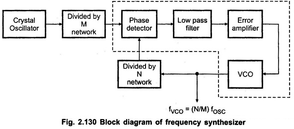
Anywho, this problem can fundamentally be tackled in both directions, depending on your priorities. The circuitry required would be almost the same either way, just differing in which divider goes where and the reference clock. It is pretty much a textbook integer-N PLL synthesizer.
Frequency-Synthesizer-Block-Diagram-001.jpg

(from here)

If you want to synthesize 8.6436 MHz but not have an undue jitter penalty, the trick is using the phenomenon of injection locking to pull the reference xtal oscillator. The downside of this being that some experimentation with levels and coupling may be required, but I'd start with a whole lotta nothing for coupling capacitance, maybe 3-5 pF. You just want PLL output to nudge the crystal oscillator on the right frequency reliably, not swamp the input and impose all the PLL phase noise onto it. An advantage of this approach is that you can just turn off power to your PLL if you want and use the player pretty much stock.
The alternative would be using an extra VCXO instead of the typical integrated CMOS VCO. But try finding an 8.6436 MHz crystal these days... (Plan B, convert the onboard XO into a VCXO. It's a bit of an odd topology so not sure how easy that would be.)

Now 16.9344 MHz / 8.6436 MHz is a ratio of 96 / 49, so you'd need an N divider of 49 and an M divider of 96.

96 = 3 * 2 * 2 * 2 * 2 * 2 or 12 * 8, so this is why a 74xx92 divide-by-12 counter (/2 + /6) and a 74xx93 4-bit binary counter (/2 + /8) come in handy.

The ANDing of 6LRCK, 6LRCK/2 and 6LRCK/6 done by Philips results in only one logic high pulse every 12 counts or 6 whole 6LRCK periods if you look at the '92 truth tables. (Not exactly sure why they found that preferable for phase detector input over piping in 6LRCK/6 straight away, but I haven't looked at the peculiarities of 4046 phase detectors in many years either.)

Either way, dividing all the way down to LRCK (i.e. 44.1 kHz) for your PLL when it could also be running at 176.4 kHz is not ideal in terms of phase noise, which is probably what that guy was getting at. And that's in addition to the general phase noise penalty if you were to replace the reference oscillator with PLL output altogether. (CMOS VCOs tend not to be phase noise kings even when they do have a nice clean supply voltage, their Q is just too low and they have a large pulling range.)

49 = 7 * 7 is a bit of a pig. That would probably take two 74xx90 decade counters in bi-quinary mode with an external AND to reset them once Qa and Qc (Q0 and Q2) go high so they don't count past 6. I'll have to consult my textbooks on whether that's correct, pretty sure I've seen something on the topic in there somewhere. (I'm not a logic guru by any means.) But that's one for tomorrow.
In case of the Philips player, the CX7934 is doing the dirty work with its LRCK output. So that's why they went with that as their PLL reference frequency, I guess.
Many, many thanks! Give in to the music, but beware of youtube.
A LOT to compute. Could you narrow it down? So there might be an advatage of using 176.4kHz for the PLL?
Any advantage to derive 16.9344MHz and 8.6436MHz from a higher frequency?
 

Vuki

Senior Member
Joined
Apr 8, 2018
Messages
343
Likes
393
Location
Zagreb, Croatia
...which would need an external clock , which would need a PLL to keep the CX7934 in sync with the transceiver.
And the output format of the CX7934 already suits most of the transceivers.
Input and output in slave mode, cd player is master to the input and transceiver to the output. The module boards on aliexpress are cheap. If you don't succeed it will not be financial disaster.
 
OP
H

Herbert

Addicted to Fun and Learning
Joined
Nov 26, 2018
Messages
530
Likes
437
Input and output in slave mode, cd player is master to the input and transceiver to the output. The module boards on aliexpress are cheap. If you don't succeed it will not be financial disaster.
1-Which module boards are you referring to?
2-The transceivers I know (CS8404/06 / DIT4096 / DIT4192) run only with
11.2896MHz = 256fs
16.9344MHz = 384fs.
22.5792MHz = 512fs
to produce SPDIF.
But the CS8421 will still output 8.6436MHz = 196 fs, in slave mode.
Or is there any output format that does not need a master clock to produce SPDIF ?
 

Vuki

Senior Member
Joined
Apr 8, 2018
Messages
343
Likes
393
Location
Zagreb, Croatia
"In Slave Mode, the left/right clock and the serial bit clock are inputs and may be asynchronous to the XTI master
clock."
 
OP
H

Herbert

Addicted to Fun and Learning
Joined
Nov 26, 2018
Messages
530
Likes
437
"In Slave Mode, the left/right clock and the serial bit clock are inputs and may be asynchronous to the XTI master
clock."
Is this also true when the Sample Rate Converter of the CS8421 is bypassed?
This also does not imply that any digital transmitter connected can be slaved completely to the CS8421 - and therefor slaved to the player.
 
Last edited:

Vuki

Senior Member
Joined
Apr 8, 2018
Messages
343
Likes
393
Location
Zagreb, Croatia
Is this also true when the Sample Rate Converter is bypassed? This also does not imply that any digital transmitter connected can be slaved completely to the CS8421 - and therefor slaved to the player.
Why would you bypass SRC? If I understood it right, ASRC was what was needed.
 
OP
H

Herbert

Addicted to Fun and Learning
Joined
Nov 26, 2018
Messages
530
Likes
437
Why would you bypass SRC? If I understood it right, ASRC was what was needed.
No - getting 1:1 SPDIF from 16bit, right justified, two's complement, MSB first.
Read my first post again.
 

Vuki

Senior Member
Joined
Apr 8, 2018
Messages
343
Likes
393
Location
Zagreb, Croatia
No - getting 1:1 SPDIF from 16bit, right justified, two's complement, MSB first.
Read my first post again.
Wouldn't it work if CS8421 is set to slave input/output, input set to RJ16bit, output to 16bit i2s and then to WM8805 HW mode, master set to 16bit i2s input (MCKL output would be 256fs=11,2896MHz)?
 
OP
H

Herbert

Addicted to Fun and Learning
Joined
Nov 26, 2018
Messages
530
Likes
437
Wouldn't it work if CS8421 is set to slave input/output, input set to RJ16bit, output to 16bit i2s and then to WM8805 HW mode, master set to 16bit i2s input (MCKL output would be 256fs=11,2896MHz)?
Then how should MCKL output of 11,2896MHz = 256fs (or16.9344MHz = 384fs or 22.5792MHz = 512fs) kept in sync with the CDP-101 internal clock, which is the slave input of CS8421?
 

Vuki

Senior Member
Joined
Apr 8, 2018
Messages
343
Likes
393
Location
Zagreb, Croatia
Then how should MCKL output of 11,2896MHz = 256fs (or16.9344MHz = 384fs or 22.5792MHz = 512fs) kept in sync with the CDP-101 internal clock, which is the slave input of CS8421?
isn't it why it is called asynchronous sample rate converter?
 
OP
H

Herbert

Addicted to Fun and Learning
Joined
Nov 26, 2018
Messages
530
Likes
437
... which it should not be.
 

AnalogSteph

Major Contributor
Joined
Nov 6, 2018
Messages
3,395
Likes
3,343
Location
.de
A LOT to compute. Could you narrow it down? So there might be an advatage of using 176.4kHz for the PLL?
Generally, the lower the reference frequency, the noisier the PLL is.
An unavoidable occurrence in digital PLL synthesis is that frequency multiplication (by N),
raises the signal’s phase noise by 20Log(N) dB.
One reason why fractional-N PLLs were invented, although those have issues of their own (notably spurii).

This also is why you don't generally want to be using a xtal oscillator with frequency multipliers to generate signals well in the GHz range.

For the modest division ratios you need, integer-N should be fine. It's a different story when you want to generate 55.995 to 85.845 MHz in 1 kHz steps (or even smaller)! (That would be a 150 kHz to 30 MHz receiver with a 55.845 MHz 1st IF, for the record.) If nothing else, something like this becomes very slow to lock as PLL bandwidth has to be very small. The traditional approach for creating even smaller steps has been using nested PLLs, which can get very complicated. More modern designs have solved some of the challenges by generating the reference frequency via DDS, which basically means a fast DAC with a sine table.

Now whether the 12 dB phase noise advantage of 176.4 kHz over 44.1 kHz (LRCK) is worth the extra circuitry and design effort needed to roll your own divider is entirely your call.
Any advantage to derive 16.9344MHz and 8.6436MHz from a higher frequency?
NAFAICS. Xtals rarely go beyond 50ish MHz anyway. The lowest common multiple of both would be 829.7856 MHz.
 
OP
H

Herbert

Addicted to Fun and Learning
Joined
Nov 26, 2018
Messages
530
Likes
437
Generally, the lower the reference frequency, the noisier the PLL is.

One reason why fractional-N PLLs were invented, although those have issues of their own (notably spurii).

This also is why you don't generally want to be using a xtal oscillator with frequency multipliers to generate signals well in the GHz range.

For the modest division ratios you need, integer-N should be fine. It's a different story when you want to generate 55.995 to 85.845 MHz in 1 kHz steps (or even smaller)! (That would be a 150 kHz to 30 MHz receiver with a 55.845 MHz 1st IF, for the record.) If nothing else, something like this becomes very slow to lock as PLL bandwidth has to be very small. The traditional approach for creating even smaller steps has been using nested PLLs, which can get very complicated. More modern designs have solved some of the challenges by generating the reference frequency via DDS, which basically means a fast DAC with a sine table.

Now whether the 12 dB phase noise advantage of 176.4 kHz over 44.1 kHz (LRCK) is worth the extra circuitry and design effort needed to roll your own divider is entirely your call.

NAFAICS. Xtals rarely go beyond 50ish MHz anyway. The lowest common multiple of both would be 829.7856 MHz.
Many many thanks! I did understand a little bit!
Either way, dividing all the way down to LRCK (i.e. 44.1 kHz) for your PLL when it could also be running at 176.4 kHz is not ideal in terms of phase noise, which is probably what that guy was getting at.
Probably someone tapped on his shoulder and said: "Sony does not use 4xOversampling yet" The CX7934 can only provide 44.1KHz for the PLL.

The ANDing of 6LRCK, 6LRCK/2 and 6LRCK/6 done by Philips results in only one logic high pulse every 12 counts or 6 whole 6LRCK periods if you look at the '92 truth tables.
You mean what I see in the circuit happening with ICs 6661 and 6662?
49 = 7 * 7 is a bit of a pig. That would probably take two 74xx90 decade counters in bi-quinary mode with an external AND to reset them once Qa and Qc (Q0 and Q2) go high so they don't count past 6. I'll have to consult my textbooks on whether that's correct, pretty sure I've seen something on the topic in there somewhere. (I'm not a logic guru by any means.) But that's one for tomorrow.
So Philips did not do this 40 years ago...? What did they do instead?
Now whether the 12 dB phase noise advantage of 176.4 kHz over 44.1 kHz (LRCK) is worth the extra circuitry and design effort needed to roll your own divider is entirely your call.
Looking at the circuit from post #1, wouldn't the design effort be less? Less division coming from 4.2336MHz, the same division / Circuit coming from 16.9344MHz. Would there be a benefit to quadruple the L/R Clock coming from CX7934 to 176.4 using a 4xmultiplier?
As I wrote, I have one or two 16.9344 Xtals (but only the simple version with two pins) as well as a 16.9344 Board that can provide 4.2336MHz as well.
IMG_2643.JPG

So bottom line, what is your advise?
Should I simply rebuild the Philips circuit and if so, are there ICs with better specs to replace the ones of the original design?
Or:
Could you propose a schematic that derives 8.6436MHz from 16.9344MHz that might have less phase noise and jitter than the Philips design?
I assume going from a higher frequency to a lower frequency is still better than the other way round.
Many thanks!
 

AnalogSteph

Major Contributor
Joined
Nov 6, 2018
Messages
3,395
Likes
3,343
Location
.de
You mean what I see in the circuit happening with ICs 6661 and 6662?
6661 and 6663 (1/4) x2.
So Philips did not do this 40 years ago...? What did they do instead?
They left that part to the CX7934. Saved them several ICs, board space and design effort.
Looking at the circuit from post #1, wouldn't the design effort be less?
Sure.

I am still puzzled by their choice of using an external VCO (the LS628) over the one in the 4046... oh, the 4046B VCO is only good for around 1 MHz (and even less at 5 V), so that explains that then. The 74HC4046A VCO can go a lot higher, well into the double-digit MHz. That chip also has a 3rd phase detector option. Definitely a good opportunity to consolidate.

Going through the List of 7400-series integrated circuits, I noticed some more potential candidates that might prove useful, like the 192 and 193, the 390 and 393 duals, or the 297 DPLL. LS and HC should generally interoperate, sometimes you can only get one any more or one is a lot cheaper. I've never had much to do with 74 series logic before, so this would be a learning opprttunity for all of us.
 
OP
H

Herbert

Addicted to Fun and Learning
Joined
Nov 26, 2018
Messages
530
Likes
437
49 = 7 * 7 is a bit of a pig. That would probably take two 74xx90 decade counters in bi-quinary mode with an external AND to reset them once Qa and Qc (Q0 and Q2) go high so they don't count past 6. I'll have to consult my textbooks on whether that's correct, pretty sure I've seen something on the topic in there somewhere. (I'm not a logic guru by any means.) But that's one for tomorrow.
So Philips did not do this 40 years ago...? What did they do instead?
They left that part to the CX7934. Saved them several ICs, board space and design effort.
The CX7934 is no divider - or did I miss anything?
Interestingly the was no need foor the Sony-made CX7034 in other Philips players that used the TDA1540 DAC,
like the very first, Philips CD-100. No clue why they needed it in the CD303 and CD200, as also the Transport, CDM-1 is the same.
Anyway, you will keep the ball rolling? Because many things are "Böhmische Dörfer" to me,
I will not be able to design a circuit that is better than the one from 40 years ago...
've never had much to do with 74 series logic before, so this would be a learning opprttunity for all of us.
Besides the fact that @restorer-john has four of the CDP-101 that could get an SPDIF output! ;-)
 

AnalogSteph

Major Contributor
Joined
Nov 6, 2018
Messages
3,395
Likes
3,343
Location
.de
The CX7934 is no divider - or did I miss anything?
I mean, it's got a 8.6436 MHz clock and a LRCK output, so there must be one in there... more specifically, consulting the schematics again, it looks like the detour through the CX7933 courtesy of WFCK may be the decisive part, as I spy a /588 divider in that one.
Anyway, you will keep the ball rolling? Because many things are "Böhmische Dörfer" to me,
I will not be able to design a circuit that is better than the one from 40 years ago...
I'll try, but can't promise anything. Due to a restructuring / merger scheduled for the beginning of the year, the time before / after xmas may leave me swamped with work, with insanity and chaos being a distinct possibility.
 
OP
H

Herbert

Addicted to Fun and Learning
Joined
Nov 26, 2018
Messages
530
Likes
437
I mean, it's got a 8.6436 MHz clock and a LRCK output, so there must be one in there... more specifically, consulting the schematics again, it looks like the detour through the CX7933 courtesy of WFCK may be the decisive part, as I spy a /588 divider in that one.

I'll try, but can't promise anything. Due to a restructuring / merger scheduled for the beginning of the year, the time before / after xmas may leave me swamped with work, with insanity and chaos being a distinct possibility.
Please, please, please do your best! I've been lingering with the idea since I bought the CDP-101 almost 10 years ago and it would be great to start soldering before Xmas.
To me, an extraordinarily circle would be closed - giving the player that started the digital revolution the means to shine with modern DACs!
 

restorer-john

Grand Contributor
Joined
Mar 1, 2018
Messages
12,734
Likes
38,968
Location
Gold Coast, Queensland, Australia
Please, please, please do your best! I've been lingering with the idea since I bought the CDP-101 almost 10 years ago and it would be great to start soldering before Xmas.
To me, an extraordinarily circle would be closed - giving the player that started the digital revolution the means to shine with modern DACs!

How is your 101 going? The tracking and servo ICs are fragile- make sure you keep the 'anti-shock' switch off- it drives more current, gets hotter and causes burnout in the marginal trackers.

I've got 4 as you say, but more interested in keeping things original for me. Got several 1st gen machines including 2x Akai CD-D1s which are absolute beasts. Twin TDA-1540s and the full Philips 1st gen chipset and a totally discrete front end. Last time I checked, only one still played. :( They don't even read or care about the TOC. LOL. I pulled them from my storeroom recently if you want to see them.
 
Top Bottom