• WANTED: Happy members who like to discuss audio and other topics related to our interest. Desire to learn and share knowledge of science required. There are many reviews of audio hardware and expert members to help answer your questions. Click here to have your audio equipment measured for free!

Very good Step Response from passive filters - without DSP!

OP
T

Trifonov Audio

Member
Audio Company
Joined
Oct 18, 2022
Messages
9
Likes
4
Location
Europe
Thank you for your attention.
This is both a product and a service - which I have published for free access to all DIY enthusiasts.
 
Last edited:

ctrl

Major Contributor
Forum Donor
Joined
Jan 24, 2020
Messages
1,633
Likes
6,243
Location
.de, DE, DEU
I offer a smart and easy way to get rid of the big ones bad Time Domain distortions - without DSP!
Can you show an example with filter slopes in VCAD? A 3-way speaker would be nice. For example a 3-way speaker with the crossover frequencies of 200Hz/2000Hz, the offset of the driver would be about 0.6m/0.06m or a corresponding delay - right? What would the filter coefficients look like to be used in a miniDSP or Hypex plateAmp?

I know for example filters according to S. Harsch, there a linear phase response without FIR is achieved by combination of Butterworth fourth oder and Bessel second order filter plus delay. Is your crossover similar to that?
 
OP
T

Trifonov Audio

Member
Audio Company
Joined
Oct 18, 2022
Messages
9
Likes
4
Location
Europe
Hi CTRL
Good questions - thanks! Before you get to sample filter slopes using Trifonov Transient Perfect and VCAD - you need to understand and agree with some important recommendations.
1) For three-way, for example - 300 Hz and about 2600 Hz.
2) Appropriate drivers
3) Offset between acoustic centers - exactly according to the published formula!
4) Sorry - I don't work with DSP. It is your responsibility to transpose the relevant coefficients.
The ultimate task for both Harsch and me is the same - an optimally linear phase and a correspondingly good Step Response.
For better flat Impulse response plateau - I use low pass 3 order and high pass has a Q factor is 0.43.
And accordingly, the formula for the distance between the acoustic centers is different.
 
Last edited:

KSTR

Major Contributor
Joined
Sep 6, 2018
Messages
2,806
Likes
6,276
Location
Berlin, Germany
I'm not able to recreate your results.

The individual TF's look OK (2nd-order low-q acoustic target for the tweeter and 3rd-order medium-q target for the woofer) but I cannot get them to sum flat.
For 1kHz XO best I can achieve is a -2.5dB ripple, with a 0.425ms delay for the tweeter (or -0.425ms for the woofer).

And 0.425ms does not match your formula of lambda/3 either as that would be 0.33ms, and with 0.33ms the sum looks really bad (-5dB dip)

1666646231303.png


1666646246169.png
 
Last edited:
OP
T

Trifonov Audio

Member
Audio Company
Joined
Oct 18, 2022
Messages
9
Likes
4
Location
Europe
If the formulas are used accurately and correctly - the linearity of the frequency band should be less than +/- 1db.
Which simulator are you using?
With Multisim and Orcad - the results are normal. Also with Vituix.

1666652857382.png


1666653024701.png


1666653071144.png
 
Last edited:

ctrl

Major Contributor
Forum Donor
Joined
Jan 24, 2020
Messages
1,633
Likes
6,243
Location
.de, DE, DEU
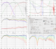
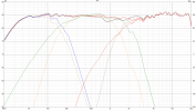
So, I did a Q&D Trifonov filter XO 180Hz/2000Hz on a 3-way speaker project of mine using VCAD based on real measurements.

Looks fine to me. Above 150Hz the GD is null and phase response is nearly linear. The overall delay of the tweeter is 2.08ms.
(The scaling is only 40dB instead of the usual 50dB, so it looks a bit wavier than it would with 50dB scaling)
1666651984694.png

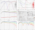
For comparison here is the Harsch filter XO 180Hz/2000Hz I use on this project. The overall delay of the tweeter is 2.95ms.
1666652480579.png

With a little more tuning, the Trifonov Filter XO should give pretty much identical results to the Harsch Filter XO, with less delay using an active XO or less driver offset with passive XO. Who needs FIR filter ;)

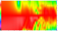
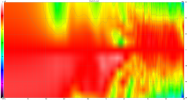
The price to be paid for this is a relatively uneven vertical radiation. This is less of a problem at the appropriate listening distance.
Vertical on-axis normalized sonogram +-90° of Trifonov and Harsch Filter XO:
1666653261372.png 1666653281934.png
 

DownUnderGazza

Active Member
Forum Donor
Joined
Jul 28, 2018
Messages
130
Likes
301
Location
New Zealand
So, if I wanted to create a near linear phase crossover for a pro audio two-way, using say a DBX DriveRack or Behringer digital crossover, how would I do it? (Where FIR filters aren’t available)

Is it simply a matter of dialing in a “combination of Butterworth fourth oder and Bessel second order filter plus delay”? (For a S. Harsch filter with near linear phase response)

I want a pretty steep HP crossover for the HF horn loaded compression driver. The bass/mid driver has reasonable upper reach, so can cope with a gentler LP slope, but will need its cone breakup notched.
 

ctrl

Major Contributor
Forum Donor
Joined
Jan 24, 2020
Messages
1,633
Likes
6,243
Location
.de, DE, DEU
Is it simply a matter of dialing in a “combination of Butterworth fourth oder and Bessel second order filter plus delay”? (For a S. Harsch filter with near linear phase response)

I want a pretty steep HP crossover for the HF horn loaded compression driver. The bass/mid driver has reasonable upper reach, so can cope with a gentler LP slope, but will need its cone breakup notched.
In principle, yes, but the filter slopes must comply with the specifications when measured acoustically***. So you need a measuring system in any case.

Crossover according to Trifonov as well as to Harsch have flat filter slopes in the high pass (this cannot be changed). This should be taken into account when choosing the crossover frequency.
Here a comparison of a 3-way speaker (see example from post#8) once phase-linear according to Harsch (or Trifonov would be very similar) and with a usual Linkwitz-Riley 4th order (the dotted lines).
1666680621104.png
Despite lower crossover frequencies in the LR4 XO, the load on the driver in the high pass is not as high.

*** Simply setting filter slopes electronically without considering the frequency response of the individual drivers in the loudspeaker will not work.

...dialing in a “combination of Butterworth fourth oder and Bessel second order filter plus delay”? (For a S. Harsch filter with near linear phase response)
For crossover frequence fc (S. Harsch filter):
high pass = Bessel 2nd order at fc + delay (1/fc * 0.5) [s] low pass = Butterworth 4th order at fc
 
Last edited:

KSTR

Major Contributor
Joined
Sep 6, 2018
Messages
2,806
Likes
6,276
Location
Berlin, Germany
If the formulas are used accurately and correctly - the linearity of the frequency band should be less than +/- 1db.
Which simulator are you using?
With Multisim and Orcad - the results are normal. Also with Vituix.
I'm using LTspice, with direct Laplace notation (which I double checked and it is in accordance with your formulas, isn't it?). I get the same result with LSPcad (the "mother" of Vituix), using the Q values provided. The simulators are sure not to blame (I'm using those two for decades now, with no issues, they are always spot on).

But... you show the result using an LCR realization of those transfer functions, not with the transfer functions directly. I have no doubts that I could recreate your results exactly with LTspice or LSPcad (or Multisim, which I seldom use, though) this way.

Therefore, I would think your derivation of the acoustic target Laplace transfer functions might be off a bit, can you elaborate how you derived the equations or even better, use them as I did, in direct form, to assert that they are valid? For example, there are gain factors in the LCR realization that are not present in the Laplace equations?

Anyhow, this XO faces the typical problem of theses approaches as pointed out by @ctrl, the broken phase tracking throughout the XO range, leading to significant directivity issues and (almost) destructive summing. And acoustic target function for the tweeter of only 2nd-order is not ideal either. IMHO best used only with beefy Coaxials.

--------:--------

Personally, I've found simple and straight LR4 acoustic target most often sounds best, and tweeter setback can be used there as well (and is implicit in many coaxials anyway) to increase the rolloff for the woofer, practically implementing a Bessel lowpass (aka constant time delay up to some frequency) to compensate the setback to get the acoustic centers aligned again. Exact phase tracking down to at least -30dB for both ways left and right of the XO point is paramount here (much more important than frequency response of the slopes) as that makes the transient behavior (using short narrow-band wavelets/blips) exactly the same for both ways, no "time-smear" widening around the XO.

It then also turns out that making that whole thing linear phase (by doing upstream global phase unwrapping via an analytically derived FIR filter kernel -- the phase response of the LR4 XO summed allpass function used backwards in time) does not sound much different. Therefore (plus from years of experience), I strongly believe exact and constant phase tracking between ways -- to whatever target, ususally 0deg but not necessarily for a coaxial or M-T-M, where (up to) 90deg constant offset also does very well and allows for steeper final slopes -- is key for precise and and fast/compact sound signature and good directivity, whereas the overall non-transient-perfect allpass function of the XO is of lesser importance.

Nonwithstanding, I do appreciate your efforts and contributions of course ;-)
 
Last edited:
OP
T

Trifonov Audio

Member
Audio Company
Joined
Oct 18, 2022
Messages
9
Likes
4
Location
Europe
I hope the LCR realization is closer to the "live" situation.
I take the Step Response observations as most important - because Multisim has a problem showing the real phase when using the delay line.
But when a good single impulse is obtained result - and the phase is good. This is evident when testing with other simulators.
Typically the phase is around +43 degrees above 1/7 of the crossover frequency is obtained.
 
OP
T

Trifonov Audio

Member
Audio Company
Joined
Oct 18, 2022
Messages
9
Likes
4
Location
Europe
P.S.
When some formulas work well - do we need to prove their mathematical origin -
through the complicateds sums and differences of integral and differential transfer functions?
 

KSTR

Major Contributor
Joined
Sep 6, 2018
Messages
2,806
Likes
6,276
Location
Berlin, Germany
Well, it is that YOU posted those Laplace transfer functions plus explaination (together with a lot of blah-blah) in an attempt to appear competent in those matters, but now to me it looks like that's just marketing decorum?

You didn't answer my question which is suspicious... either you can explain and povide detail how arrived at those equations or you can't.

Normally that's a very easy task as the simulators (like LPScad and Vituix) spit out the transfer functions right away once you found a nice combination of atomic building blocks (LP/HP/delay/etc) that give the desired result because that's the workflow how one actually "invents" new crossover types.
Realization into active or passive circuits is step that follows after that.

An example:
1666852802514.png

This is a transient-perfect linear-phase 4th-order crossover at 3kHz, using a bit of tweeter setback and, more importantly, phase-compensating allpass cells on the tweeter. As we can see, pretty much perfect flat phase up to 20kHz and a clean -6dB point which indicates at least fair phase offset between ways.

Phase plot:
1666853090670.png

At the XO point phase tracking is ~30deg off but gets better above XO (intersect at 4kHz) where it is more important for lobing. In general, within the whole XO range (down to -20dB) the phase tracking is no worse that ~60deg which prevents any destructive summing.

Step (square) response:
1666853391547.png

Textbook perfect as phase plot already indicated. The high-frequency "pre-ripple" is coming from a 96kHz sampling frequency in the sim and the allpass correction stopping to be effective above 20kHz which then results in (inaudible) content above 20kHz being too early in time.

Filter setup:
1666853583694.png

TF12, 10 and 11 are the allpass cells given in Matlab Laplace notation thus not directly visible whats going on here but for the rest the transfer function data is given in direct form (using Q factors).

----------:-----------

IHMO, that's the kind of data you should be able to provide if you want to be taken seriously.
 
OP
T

Trifonov Audio

Member
Audio Company
Joined
Oct 18, 2022
Messages
9
Likes
4
Location
Europe
Dear KSTR,
Everyone has the right to be suspicious and doubtful. Any good mathematician can arrive at the "easy" answers to equations on their own.
I'm not a good mathematician - I'm a sound engineer and musician. Isn't it more important to get to the right task and then have our colleague (expert)
do what needs to be done (the simple arithmetic).
 

dualazmak

Major Contributor
Forum Donor
Joined
Feb 29, 2020
Messages
2,866
Likes
3,082
Location
Ichihara City, Chiba Prefecture, Japan
In principle, yes, but the filter slopes must comply with the specifications when measured acoustically***. So you need a measuring system in any case.
*** Simply setting filter slopes electronically without considering the frequency response of the individual drivers in the loudspeaker will not work.

I essentially agree with your points.

Even though I am not a sound engineer and I am not a mathematician, I would like to objectively "measure" the room air sound mainly at my listening position in my own listening room environment using well understandable (for myself), validated, reproducible measurement methods.

This is why I use rather primitive "cumulative white noise averaging method" for Fq-response measurements (please refer to my summary post here); I also developed my own primitive methods for "precision time alignment measurement and tuning" (please refer to my summary post here).

I assume and believe all of the "theoretical" efforts, mathematical and/or engineering, should be finally validated/evaluated not only by objective room air sound measurements but also by our subjective music listening tests using our own audio gears in our own room acoustics using our own "audio sampler reference music tracks (such as my audio sampler playlist)".
 

KaiHam

New Member
Joined
Apr 19, 2024
Messages
1
Likes
0
There is a simple reason for the disagreement of KSTR's simulation results with LTSpice and the results of Trifonov and others:
As shown in contribution #6 he used a negative delay time td= -0.425 ms.
The delay has to be positive. LTSpice allows negative (non-causal) delays in AC-analysis but not in transient response analysis.
With a positive td=0.333ms the results are closer to Trifonovs (but not exactly equal, what may be due to other small differences in the models).
 

Ze Frog

Addicted to Fun and Learning
Joined
Jan 4, 2024
Messages
640
Likes
729
Am I missing something here? Only can't this all be done when designing a crossover from measured driver attributes on baffle, designing crossover and then measuring and adjusting as needed? Seems like something that already has a solution.
 
Top Bottom