I'm not saying that mirroring doesn't happen. I'm saying that in DA (or upsampling) it doesn't affect the 0-22k band if you don't filter out the mirror images from >22k band. No, you won't recover the signal, as a whole, as it was before sampling, but the 0-22k part of the signal will be the same.
Usually here on ASR, when someone corrects those who say that images reflect back to 0-22k in DA process, like
here or
here ")
I don't know, nothing I read about sampling theorem ever implied to me that images reflect back, so it's rather hard to point out any source that explicitly says that it does or doesn't happen.
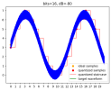
But I can actually show what I described previously. Here's a 24/44k multitone generated by REW (in attachment):
View attachment 409175
I can upsample it using a steep filter with 20k-22k transition band and with a shallow filter with 20k-28k transition band:
Code:
sox "mt.input.wav" -r88200 -b32 "mt.fast.wav" upsample 2 sinc -a 170 -t2k -21k vol 2
sox "mt.input.wav" -r88200 -b32 "mt.slow.wav" upsample 2 sinc -a 170 -t8k -24k vol 2
View attachment 409176
View attachment 409177
As far as I understand what you are saying, there should be some difference between them in 16k-22k band? Null shows only the images:
Code:
sox -m -v1 "mt.fast.wav" -v -1 "mt.slow.wav" "mt.null.wav"
View attachment 409178
And at this point this signal is like any other signal sampled at 88.2k. The images became part of it and there isn't any special relation between 0-22k and 22k-44k bands anymore.
If I had to guess, I'd say that's because they are using halfband filters. An advantage of halfband filters is that every other coefficient is 0, so this is very desirable because it reduces costs. A disadvantage is that they can only be centered around Fs/4. That means that when you use them in x2 upsampling to 88'200, then 22'050 lies right in the middle of the transition band. And there's where you get 20k-24k transition band.
For an example, there are 2 filters in attachments [1]:
- The halfband filter with 20k-24k transition band, 100 dB stopband attenuation and 0.0001 dB passband ripple; it has 131 taps and only 67 of them non-zero.
- The steep filter with the same stopband attenuation and passband ripple but only 20k-22k transition band; it has 263 taps and none of them 0.
So that's 4x difference in non-zero taps [2]. This, I assume, translates to costs, size, power consumption, etc, and these are probably deemed too much for what they offer.
Code:
sox "impulse.wav" -r88200 "impulse.halfband.wav" upsample 2 fir "fir.halfband.txt" vol 2
sox "impulse.wav" -r88200 "impulse.steep.wav"    upsample 2 fir "fir.steep.txt"    vol 2
View attachment 409185
View attachment 409186
[1] The filters were created by following these blog posts
Designing Generic FIR Filters with pyFDA and NumPy and
Half-Band Filters, a Workhorse of Decimation Filters
[2] AFAIU, these filters should be optimal, but I'm just a dude on the internet, so maybe something better is possible
. But I don't think the improvement could be significant without changing filter characteristics.